
 E-mail Alert
 RSS
RSS-
Abstract
The characteristics of reflected light of a 1-D guided-mode resonance filter (GMRF) are studied in this paper. A triple-layer GMRF is designed by using the finite difference time domain method under non-polarized light illumination. Numerical results show that the reflectance spectra of TE and TM polarizations can be changed by altering the fill factor f of the GMRF. Moreover, by calculating the color of the reflected light with the chromaticity theory, we find that the color of reflected light becomes pure when f is 0.9. The results show that the color and polarization degree of the reflected light of a GMRF are tunable by altering the fill factor.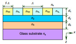
-
1. Introduction
In this paper, the reflection spectrum of a GMRF is calculated using the finite difference time domain (FDTD) method. Then the reflection spectra of TE polarization and TM polarization with different fill factor are studied under non-polarized light illumination. The numerical results show that reflection spectra for TE and TM polarizations under the same GMRF period are different and the color of reflective light is not pure. By altering the fill factor f of the GMRF, the color and polarization degree of the reflected light are turned and the reflected light color becomes pure when the fill factor is 0.9. The results of this paper can provide references for the design and fabrication of GMRFs.
Color filters are useful for image sensors, display devices, and many other applications. Traditional color filters use colorant-based materials to achieve a desired color spectrum, which transmit a particular color while absorbing the undesired surrounding spectrum under white light illumination. Such color filters undergo performance degradation under long-duration ultraviolet irradiation or at high temperature. Moreover, problems with colorant-based filters include low transmission efficiency, heating due to absorption of light, and imperfect color purity. Technologies to improve color filter have led to researches on diffractive gratings color filters[1-6]. The guided-mode resonance filter (GMRF) that consists of a surface-relief grating and thin-film waveguides is a promising optical element. The GMRF attracts a lot of interest because of its super wavelength-selecting ability. The guided-mode resonance is due to the excitation of leaky guided modes in the periodic waveguide structure. Thus, lossless spectral filters with very narrow and tunable bandwidth appear to be feasible by using GMRFs. Moreover, the GMRFs with different resonance wavelengths are able to be obtained by changing the grating period. The previous research results mainly focus on the reflectance of GMRFs under TE polarized light illumination[1-7]. However, the reflectance of a 1-D GMRF depends greatly on the polarization modes of the incident light, and the resonance wavelength of TE polarized light is generally different from that of TM polarized light. As natural light can be considered as the superposition of TE polarization and TM polarization, the reflection efficiencies of TE and TM polarizations are different. Thus the color of reflected light of a 1-D GMRF is a combination of TE and TM polarizations, and the reflected light becomes partially polarized light. Unfortunately, previous research results can not weaken resonance peak from TE and TM polarizations by altering the period of GRMFs.
2. Theoretical analyses
where ρTE(λ) and ρTM(λ) are the reflectance of TE polarization and TM polarization, respectively. After ρTE(λ) and ρTM(λ) of the GMRF shown in Fig. 1 are calculated by using the FDTD method, the color of reflected light can be studied by the chromaticity theory. The Commission Internationale de l'Eclairage (CIE) tristimulus values XYZ are obtained as [10]:
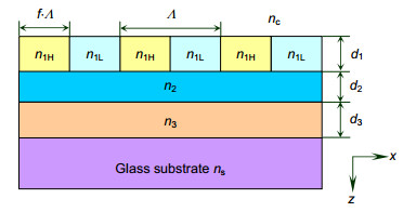
Typically, a GMRF consists of a surface-relief grating and thin-film waveguides, and a triple-layer GMRF can acquire very narrow resonance bandwidth under polarized light illumination. As shown in Fig. 1, a triple-layer GMRF comprises a grating layer, two waveguide layers, and a substrate. From top to bottom, the GMRF analysis model includes a cover layer (nc=1.0, air), a grating layer (n1H=1.62, photoresist, n1L=1.0, air), film layer 2 (n2=2.02, Si3N4 [7]), film layer 3 (n3=1.85, ITO[8]), and a substrate layer (ns=1.5, glass).
According to the effective media theory (EMT)[9], the effective refractive indices of TE polarization and TM polarization of the grating layer are given by:
Then, the value R can be calculated by Eq. (6) and the value G, B can be calculated in the same way. Thus, the color of the reflected light of a GMRF can be obtained by RGB values.
From Eqs. (1) and (2), the resonance wavelength of TE polarized light is different from that of TM polarized light because of the different effective refractive indices. As natural light can be regarded as the superposition of TE polarization and TM polarization, the reflected light is probably partially polarized light. The polarization degree of reflected light is obtained as:
where x(λ), y(λ), z(λ) are the CIE 1964 spectral tristimulus values, and S(λ) is the energy distribution of CIE standard illuminant D65[11]. After a linear transformation shown in Eq. (5), the linear values Rliner, Gliner and Bliner can be obtained.
3. Results and discussion
3.1 Reflectance with different Λ
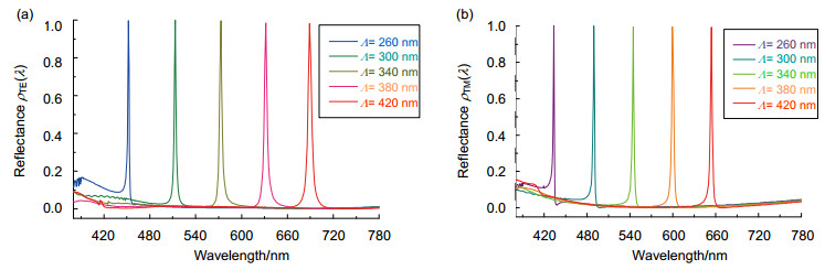
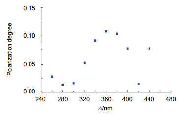
The triple-layer GMRF in Fig. 1 is designed using a commercially available FDTD solution from Lumerical, Canada. The parameters are f=0.5 (fill factor), d1=119 nm, d2=71 nm, and d3=75 nm under non-polarized light illumination. By altering the period Λ of the GMRF, we can obtain different resonance wavelengths for TE and TM polarizations. The reflection spectra of the GMRF with different Λ of 260 nm, 300 nm, 340 nm, 380 nm and 420 nm are shown in Fig. 2. We can see that the resonance wavelengths increase with the Λ. However, the reflection spectra of TE and TM polarizations under the same period Λ are different. The polarization degree of reflected light can be calculated by Eq. (3). The polarization degrees of light reflected by the GMRF with Λ of 260 nm, 300 nm, 340 nm, 380 nm and 420 nm are shown in Fig. 3.It is obvious that the reflected light of the GMRF becomes partially polarized light under non-polarized light illumination.
![Figure 2. Reflection spectra of the GMRF with Λ of 260 nm, 300 nm, 340 nm, 380 nm and 420 nm. (a) TE polarization. (b) TM polarization.]() Figure 2.
Figure 2.Reflection spectra of the GMRF with Λ of 260 nm, 300 nm, 340 nm, 380 nm and 420 nm. (a) TE polarization. (b) TM polarization.
![Figure 3. Polarization degree of the reflective light with Λ of 260 nm, 300 nm, 340 nm, 380 nm and 420 nm.]() Figure 3.
Figure 3.Polarization degree of the reflective light with Λ of 260 nm, 300 nm, 340 nm, 380 nm and 420 nm.
3.2 Reflectance with different f
![Figure 4. Reflection spectra and colors of the GMRF with f of (a) 0.1, (b) 0.25, (c) 0.5, (d) 0.75 and (e) 0.9.]() Figure 4.
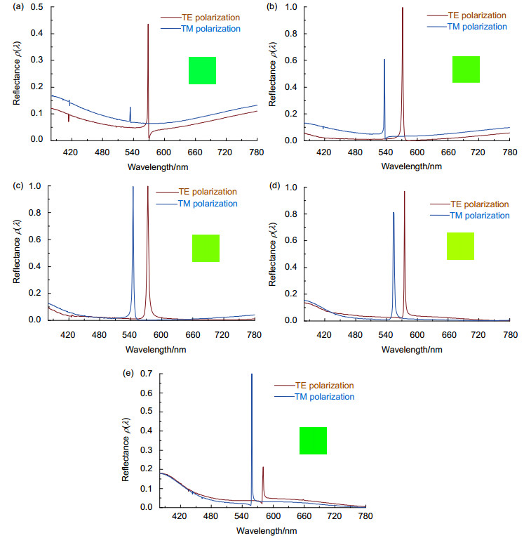
Figure 4.Reflection spectra and colors of the GMRF with f of (a) 0.1, (b) 0.25, (c) 0.5, (d) 0.75 and (e) 0.9.
The peak values of TE and TM reflectances are both equal to 1 when f is 0.5, however, the two strong resonance spectra lead to high color mixing in the reflected light. Unfortunately, we cannot weaken peak reflectance from TE and TM polarizations by altering the period Λ of GRMF. From Eqs. (1) and (2), the effective refractive indices of TE and TM polarizations are determined by f, thus we can change f to weaken one reflectance peak from TE and TM polarizations.
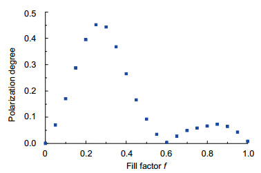
The reflection spectra and colors of the GMRF are shown in Fig. 4. The parameters are Λ=340 nm, d1=119 nm, d2=71 nm, d3=75 nm, f =0.1, 0.25, 0.5, 0.75 and 0.9. We can see that the gap between ρTE(λ) and ρTM(λ) widens by altering f of the GMRF. The total reflectance ρ(λ) of the GMRF is the sum of ρTE(λ) and ρTM(λ), and the color of reflected light of GMRF can be obtained from Eqs. (4)~(6). The numerical results in Fig. 4 show that the color of reflected light becomes pure when f is 0.9. The relationship between polarization degree and f of the GMRF is shown in Fig. 5. It is obvious that the polarization degree drops to 0.1 or lower when f is larger than 0.5.
![Figure 5. Polarization degree of the reflected light of GMRF with different fill factors.]() Figure 5.
Figure 5.Polarization degree of the reflected light of GMRF with different fill factors.
4. Conclusions
In this paper, the reflection characteristics of triple-layer GMRFs under non-polarized light illumination are studied using the FDTD method. Through a large amount of numerical calculations and simulations, the parameters of GMRFs are acquired. It is clear that the reflection spectra of TE and TM polarizations under the same period Λ are different. Furthermore, the reflection spectra of TE polarization and TM polarization can be changed by altering the fill factor f. By calculating the color of the reflected light with the chromaticity theory, we find that the color of reflected light becomes pure when f is 0.9. The results show that the color and polarization degree of the reflected light of GMRFs are tunable by altering the fill factor.
Acknowledgements:This work was supported by the National Natural Science Foundation of China (61605035). We thank Xiyang Zhi for providing us constructive idea.
-
参考文献
Katchalski T, Levy-Yurista G, Friesem A A, et al. Light modulation with electro-optic polymer-based resonant grating waveguide structures[J]. Optics Express, 2005, 13(12): 4645‒4650.
DOI: 10.1364/OPEX.13.004645Mehta A A, Rumpf R C, Roth Z A, et al. Guided mode resonance filter as a spectrally selective feedback element in a double-cladding optical fiber laser[J]. IEEE Photonics Technology Letters, 2007, 19(24): 2030‒2032.
DOI: 10.1109/LPT.2007.908776Vogel M M, Rumpel M, Weichelt B, et al. Single-layer resonant-waveguide grating for polarization and wavelength selection in Yb: YAG thin-disk lasers[J]. Optics Express, 2012, 20(4): 4024‒4031.
DOI: 10.1364/OE.20.004024Xiao Guohui, Zhu Qiangzhong, Shen Yang, et al. A tunable submicro-optofluidic polymer filter based on guided-mode resonance[J]. Nanoscale, 2015, 7(8): 3429‒3434.
DOI: 10.1039/C4NR07233B展开 -
版权信息
版权属于中国科学院光电技术研究所,但文章内容可以在本网站免费下载,以及免费用于学习和科研工作 -
关于本文
出版历程
- 收稿日期 2017-07-11
- 修回日期 2017-09-09
- 刊出日期 2017-11-14
文章计量
访问数(6778) PDF下载数(2110)
- 6778 访问数
- 2110 下载数
 下载:
下载: