E-mail Alert
 RSS
RSS-
Abstract
Due to the limitations of spatial bandwidth product and data transmission bandwidth, the field of view, resolution, and imaging speed constrain each other in an optical imaging system. Here, a fast-zoom and high-resolution sparse compound-eye camera (CEC) based on dual-end collaborative optimization is proposed, which provides a cost-effective way to break through the trade-off among the field of view, resolution, and imaging speed. In the optical end, a sparse CEC based on liquid lenses is designed, which can realize large-field-of-view imaging in real time, and fast zooming within 5 ms. In the computational end, a disturbed degradation model driven super-resolution network (DDMDSR-Net) is proposed to deal with complex image degradation issues in actual imaging situations, achieving high-robustness and high-fidelity resolution enhancement. Based on the proposed dual-end collaborative optimization framework, the angular resolution of the CEC can be enhanced from 71.6" to 26.0", which provides a solution to realize high-resolution imaging for array camera dispensing with high optical hardware complexity and data transmission bandwidth. Experiments verify the advantages of the CEC based on dual-end collaborative optimization in high-fidelity reconstruction of real scene images, kilometer-level long-distance detection, and dynamic imaging and precise recognition of targets of interest.
Keywords
-
Introduction
Modern optical imaging systems are expected to have characteristics of large field of view, high resolution, and fast imaging speed1−6. However, due to the limitations of spatial bandwidth product and data transmission bandwidth, field of view, resolution, and imaging speed constrain each other in an optical imaging system7−9. Insect compound eye is a multi-aperture visual perception organ composed of numerous ommatidia, providing solutions to break the spatial bandwidth product limitation of traditional single-aperture imaging systems10−15. Inspired by the insect compound eye, many artificial compound-eye array cameras have been developed and possible to achieve both large field of view and high resolution16−18. However, the dense sub-camera array not only generates massive amounts of data, but also leads to a dramatic increase in system size, weight, and power consumption, which severely limits the imaging speed and portability of the system.
To solve these issues, some representative works have been proposed in recent years. Some researchers proposed compound-eye array cameras with multi-scale optical structures, where the array cameras share a large-scale objective lens at the front end19−22. This reduces the number of lenses and improves the compactness of the system to a certain extent, while ensuring a large aperture and achieving well aberration correction. Some researchers proposed array cameras consisting of two types of sub-cameras with different resolutions, which can operate with active selective local high-resolution imaging within a large field of view, reducing data transmission bandwidth demand by adaptively allocating image resources23,24. In addition, achieving non-uniform resolution imaging modes through irregular arrangement of different types of lenses also provides a solution to achieve large field-of-view imaging and improve imaging speed25,26. However, the demands for a large number of image sensors with high pixel density, or a mass of lens units are always inevitable. Therefore, it is still challenging to achieve large field of view, high resolution, and fast imaging speed with low optical hardware complexity and data transmission bandwidth.
In fact, zoom imaging has been widely used to deal with the conflict between field of view and resolution. Zoom imaging systems can obtain high resolution images of key targets using limited photosensitive pixels by adjusting the imaging focal length27,28. Introducing zoom function in compound-eye array cameras will be of great significance in reducing the number of sub-cameras and alleviating the demand of data transmission bandwidth while maintaining the large field of view and high-resolution imaging capability. However, the zoom mode through mechanically moving lens group lacks fast adjustment speed, usually costing several seconds, and requires high complexity causing a relatively large volume and weight. Liquid lenses emerging in recent years have attracted much attention due to the fast focusing characteristics and high compactness29−32, but the design method of zoom imaging systems based on liquid lenses still needs further exploration. Moreover, zoom imaging systems still suffer degradation of imaging quality caused by many factors such as insufficient aberration correction, manufacturing tolerance and environmental interference. Some deep learning based super-resolution algorithms that do not rely on optical hardware have achieved impressive results, but they may be inevitably constrained by generalization33−35. And although point spread function engineering has good interpretability36−38, it often necessitates a complex calibration and iterative calculation process, with executing difficulty increasing sharply with the number of sub-cameras in compound-eye array cameras. In summary, fast zoom and high-fidelity resolution enhancement are crucial for compound-eye array cameras, because of the potential to deal with the conflict among the field of view, resolution, and imaging speed.
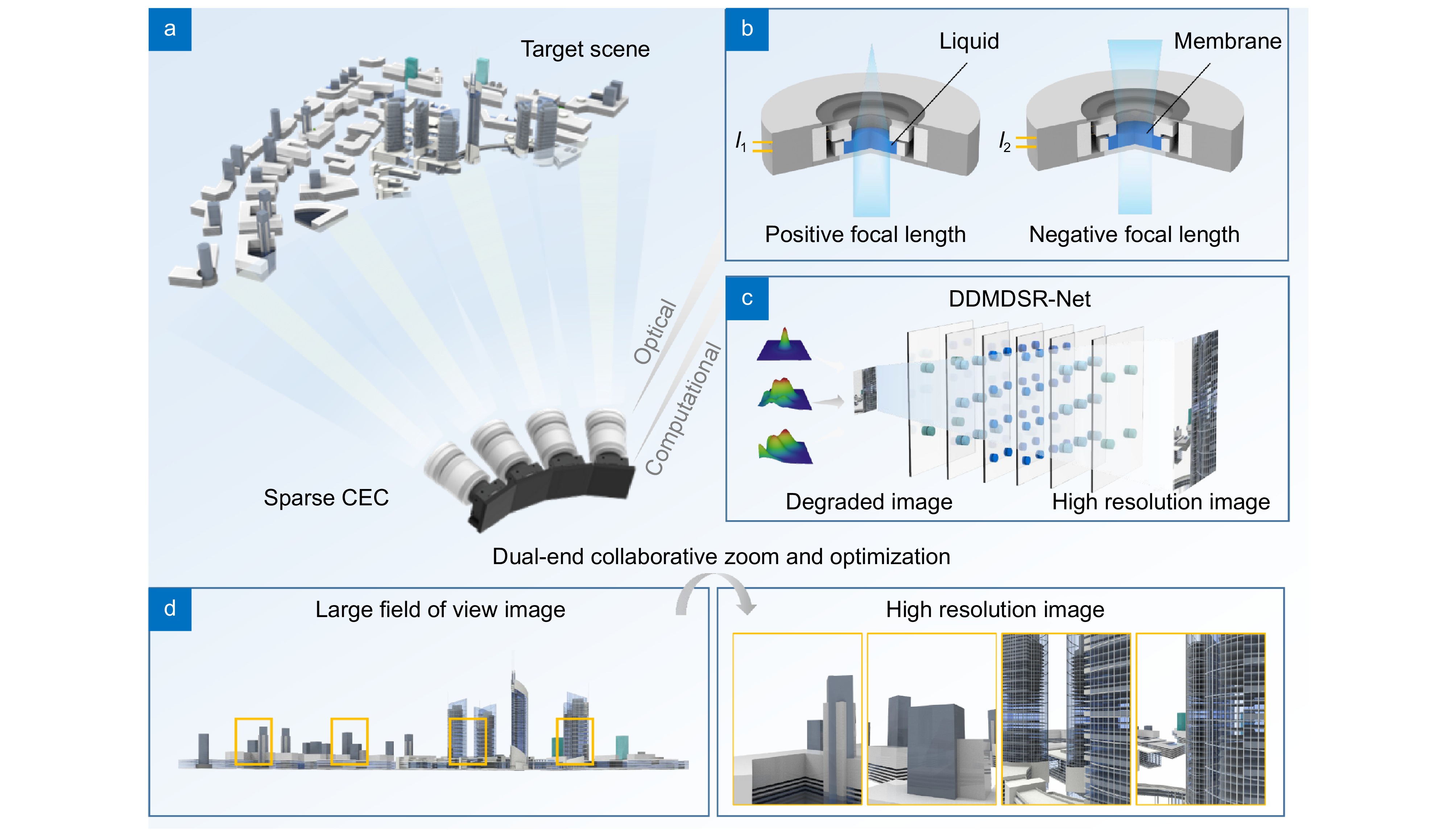
Here, a fast-zoom and high-resolution sparse compound-eye camera (CEC) based on dual-end collaborative optimization is proposed, which provides a cost-effective way to break through the trade-off among the field of view, resolution, and imaging speed, as shown in Fig. 1. Through fast zooming of the optical end and information demodulation of the computational end, the designed sparse CEC can achieve both real-time large-field-of-view imaging and high-resolution imaging. Specifically, in the optical end, a sparse CEC based on liquid lenses is designed, which can achieve fast adjustment of imaging magnification and aberrations. Each sub-camera of the CEC has a field of view more than 15.8° × 11.8° and 2× optical zoom imaging capability, with a zoom response time of only 5 ms. In the computational end, a disturbed degradation model driven super-resolution network (DDMDSR-Net) is proposed, which achieves high-robustness and high-fidelity resolution enhancement. By introducing an imaging degradation model considering environment interference, manufacturing tolerance and acquisition noise, the trained DDMDSR-Net is well suited for the resolution enhancement of the proposed CEC without complex calibration processes. Moreover, a channel attention mechanism is used during the training and reconstruction process of the DDMDSR-Net, ensuring the strong capability of feature information extraction. Through the collaborative zoom and optimization of both the optical and computational ends, the angular resolution of the CEC can be enhanced from 71.6" to 26.0", dispensing with high optical hardware complexity and data transmission bandwidth. Experiments verify the advantages of the CEC in high-fidelity reconstruction of real scene images, kilometer-level long-distance detection, and dynamic imaging and precise recognition of targets of interest. The proposed CEC has important application value in fields such as geodesy, search and track, and urban traffic monitoring.
![Figure 1. Concept of fast-zoom and high-resolution sparse CEC based on dual-end collaborative optimization. (a) Schematic diagram of imaging scene and the proposed sparse CEC based on liquid lenses. (b) Structure and zoom principle of the liquid lens. (c) Schematic diagram of the proposed DDMDSR-Net. (d) Schematic diagram of the imaging characteristics of the proposed sparse CEC.]() Concept of fast-zoom and high-resolution sparse CEC based on dual-end collaborative optimization. (a) Schematic diagram of imaging scene and the proposed sparse CEC based on liquid lenses. (b) Structure and zoom principle of the liquid lens. (c) Schematic diagram of the proposed DDMDSR-Net. (d) Schematic diagram of the imaging characteristics of the proposed sparse CEC.
Concept of fast-zoom and high-resolution sparse CEC based on dual-end collaborative optimization. (a) Schematic diagram of imaging scene and the proposed sparse CEC based on liquid lenses. (b) Structure and zoom principle of the liquid lens. (c) Schematic diagram of the proposed DDMDSR-Net. (d) Schematic diagram of the imaging characteristics of the proposed sparse CEC.Results and discussion
Principle of the sparse CEC based on dual-end collaborative optimization
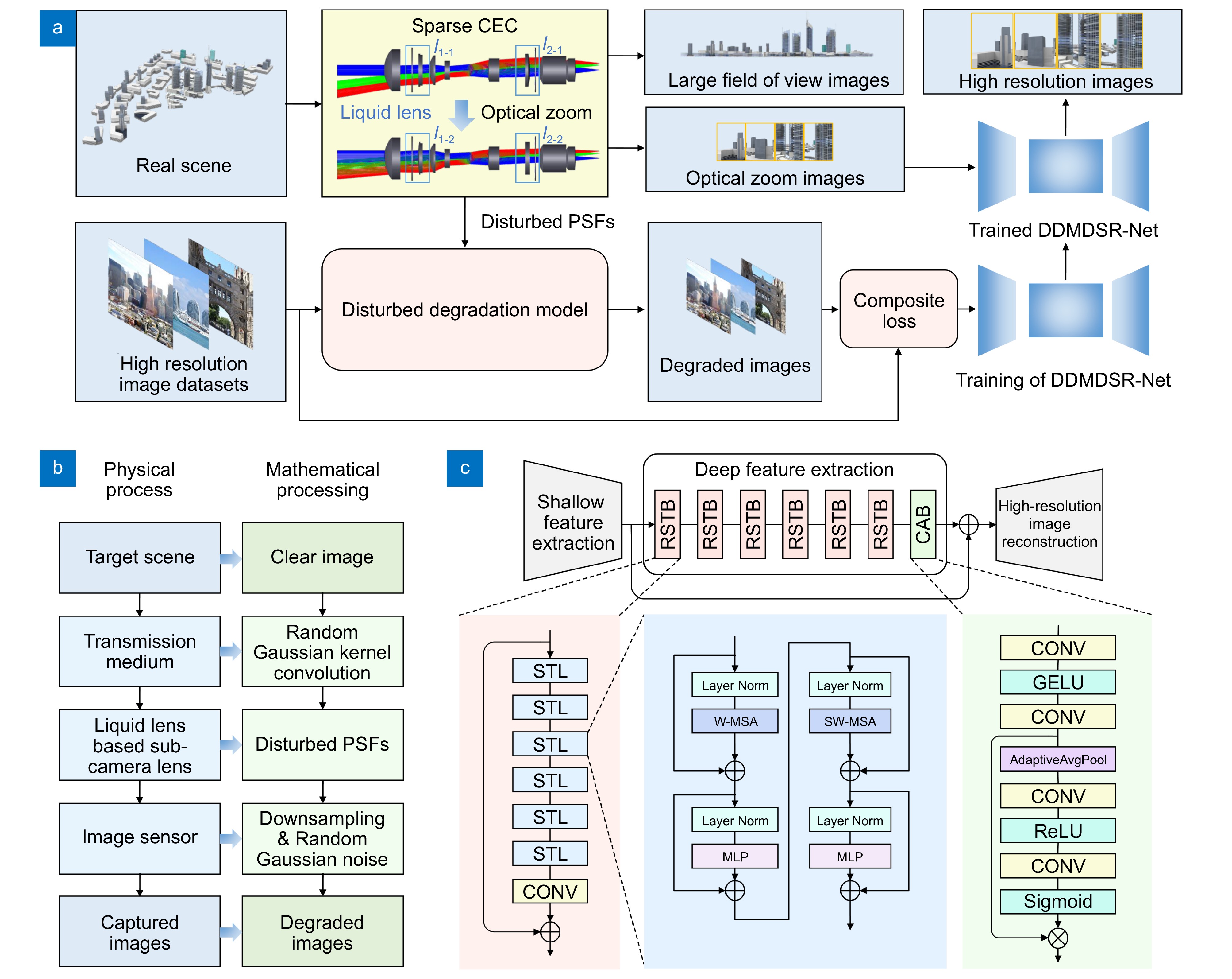
The core of the sparse CEC based on dual-end collaborative optimization is to achieve resolution enhancement through the collaboration of fast zooming in the optical end and information demodulation in the computational end. This strategy allows the proposed CEC to operate using sparse sub-camera array and image sensors with limited pixel density, ensuring low optical hardware complexity and data transmission bandwidth. Meanwhile, the large-field-of-view and high-resolution imaging can also be achieved. The workflow diagram of the sparse CEC based on dual-end collaborative optimization is shown in Fig. 2(a). Firstly, the sub-cameras of the sparse CEC are used to capture images of different regions, which can be stitched to form large field of view images. Then, by controlling the liquid lenses in the sub-cameras, the imaging magnification and aberrations of the sub-cameras can be fast adjusted to obtain zoom images with wider information frequency domain. Through the reconstruction by the proposed DDMDSR-Net, the resolution of the images can be further improved.
![Figure 2. Fast-zoom and high-resolution imaging mechanism of the proposed sparse CEC. (a) Dual-end collaborative optimization framework. (b) Architecture of disturbed degradation model and generation of image training pairs. (c) DDMDSR-Net using a multi-channel attention mechanism.]() Fast-zoom and high-resolution imaging mechanism of the proposed sparse CEC. (a) Dual-end collaborative optimization framework. (b) Architecture of disturbed degradation model and generation of image training pairs. (c) DDMDSR-Net using a multi-channel attention mechanism.
Fast-zoom and high-resolution imaging mechanism of the proposed sparse CEC. (a) Dual-end collaborative optimization framework. (b) Architecture of disturbed degradation model and generation of image training pairs. (c) DDMDSR-Net using a multi-channel attention mechanism.At the optical end, the liquid lens based sparse CEC is designed, composed of multiple identical sub-cameras arranged on a curved surface. By reasonably setting the angle between the optical axes of the sub-cameras to be slightly smaller than the maximum field of view of the sub-camera, there is an overlap between the fields of view of the sub-cameras, allowing for stitching of large field of view images. By pre-calibrating the homography between the sub-images captured by the sub-cameras and the large field of view images, and combined with adjustments of image brightness and white balance coefficient, stitched large field of view images can be generated. Each sub-camera contains several liquid lenses and solid lenses, and the focal length as well as imaging aberrations can be adjusted by controlling the liquid interfaces of the liquid lenses, which is different from traditional zoom methods that rely on the movement of lens groups. Specifically, the liquid lens are driven by a voice coil motor, which squeezes the cavity through Ampere's force and causes deformation of the liquid interface, thus realizing zoom function. Therefore, the zoom response time of the designed sparse CEC based on liquid lenses can achieve millisecond level. When executing specific design, we use four sub-cameras to form the CEC as an example (Supplementary information Section 1). Each sub-camera contains two liquid lenses, four single solid spherical lenses and two spherical doublet lenses, operating with a field of view more than 15.8° × 11.8° and 2× optical zoom imaging capability. The two liquid lenses are located in the zoom group and compensation group, respectively, with sufficient spacing between them, so as to achieve sufficient modulation of the optical power of the sub-camera.
At the computational end, the DDMDSR-Net is designed to deal with complex image degradation issues in actual imaging situations and achieve further resolution enhancement. A disturbed degradation model is first built for the training datasets generator, considering the composite degradation factors of transmission medium, lens aberration, and image acquisition. The physical process and corresponding mathematical description of the disturbed degradation model are shown in Fig. 2(b), and the imaging degradation process can be represented as
I(x,y)=[PSF(x,y)⊗T(x,y)⊗O(x,y)]↓+N(x,y), (1) where I(x, y) and O(x, y) represent degraded image and original image, respectively, T(x, y) is the degradation function of the transmission medium, PSF(x, y) is the degradation function of the sub-camera lens also called point spread function (PSF), ↓ represents down-sampling process of the image sensor, and N(x, y) is the noise. The degradation functions and noise are set to vary according to the random disturbed factors, rather than being set as fixed functions, so as to deal with various complex degradation scenarios. Specially, Monte Carlo method is used to generate the degradation functions of the sub-camera lens, which can be expressed as
PSF(x,y)=PSFMonte(idealPSF(x,y),d1,d2,...,dn), (2) where idealPSF(x, y) is the ideal PSF without disturbance degradation, and d1, d2, ... , dn represent values of a set of predefined disturbance factors related to manufacturing tolerances of the lenses and wavefront errors of the liquid lenses. The details of image degradation processing and specific settings can refer to Supplementary information Section 2. Combining high resolution image datasets with the proposed disturbed degradation model, training pairs can be easily generated for supervised learning of the DDMDSR-Net.
The DDMDSR-Net consists of three modules: shallow feature extraction module, deep feature extraction module, and image reconstruction module, as shown in Fig. 2(c). Among them, the shallow feature extraction module consists of 3×3 convolution layers, which are used to extract shallow information from the image and expand the dimension of the feature space. The deep feature extraction module consists of six residual Swin Transformer blocks (RSTBs) and one channel attention block (CAB), which are used to further extract features in high dimensional space39. The details of the network can refer to Methods and Supplementary information Section 3. Through the reasonable generalization brought by the proposed disturbance degradation model and the strong feature extraction ability of the network, high-robustness and high-fidelity resolution enhancement can be achieved. Such strategy is well suited for the resolution enhancement of the CEC with multiple identical sub-cameras, dispensing with complex calibration processes.
Fabrication and basic imaging performance test
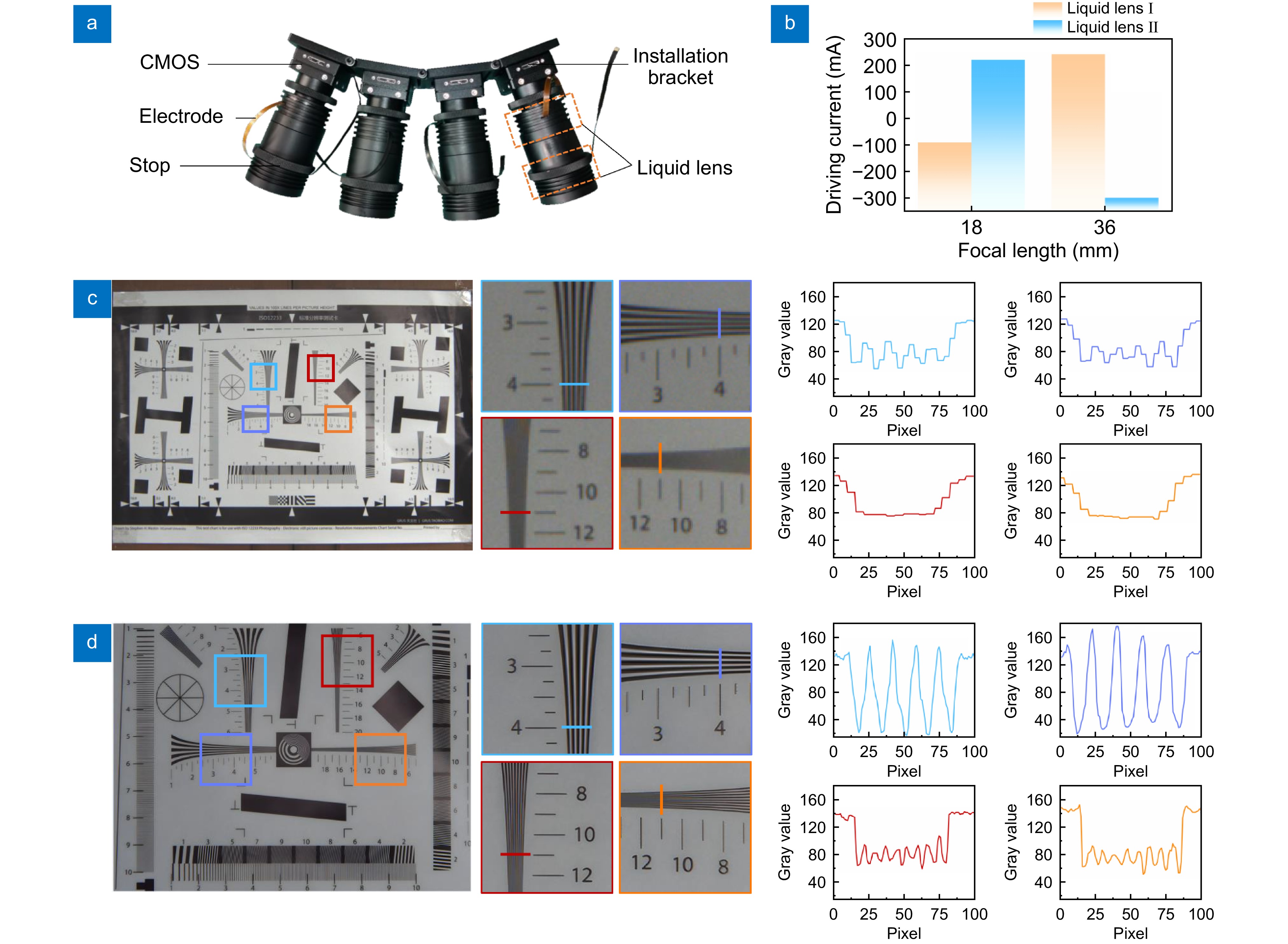
According to the above design, a prototype of the sparse CEC is fabricated, as shown in Fig. 3(a). Each solid lens in the sub-cameras is coated with a visible light band anti-reflective film, and each sub-camera contains two liquid lenses with the type of EL-12-30-TC provided by Optotune Switzerland AG. The low bandwidth image sensor with the type of VEN-161-61U3C provided by Daheng Imaging Inc. has a resolution of 1080×1440, and supports a maximum frame rate of 61.2 fps for image acquisition. Four sub-cameras are fixed on an installation bracket, the mechanical length of each sub-camera is within 10 cm and the weight is approximately 250 g. And each sub-camera can be independently or synchronously driven to achieve zoom function through a customized current driver. In the experiment, we mainly control the sparse CEC to switch between two critical focal length states with a fastest response time of approximately 5 ms, and the relationship between driving currents and focal length is shown in Fig. 3(b).
![Figure 3. Fabrication and imaging performance test of the proposed sparse CEC. (a) Prototype of the proposed sparse CEC. (b) Relationship between the driving currents of the liquid lenses and the focal length of the sub-camera. (c) Large field of view image of the resolution target captured by a sub-camera in the CEC. (d) High resolution image of the resolution target through the dual-end collaborative zoom and optimization.]() Fabrication and imaging performance test of the proposed sparse CEC. (a) Prototype of the proposed sparse CEC. (b) Relationship between the driving currents of the liquid lenses and the focal length of the sub-camera. (c) Large field of view image of the resolution target captured by a sub-camera in the CEC. (d) High resolution image of the resolution target through the dual-end collaborative zoom and optimization.
Fabrication and imaging performance test of the proposed sparse CEC. (a) Prototype of the proposed sparse CEC. (b) Relationship between the driving currents of the liquid lenses and the focal length of the sub-camera. (c) Large field of view image of the resolution target captured by a sub-camera in the CEC. (d) High resolution image of the resolution target through the dual-end collaborative zoom and optimization.To test the basic imaging performance, the sparse CEC is used to capture images of a resolution target. The images captured by one of the sub-cameras before and after dual-end collaborative zoom and optimization are shown in Fig. 3(c, d), being taken as an example. It can be tested that the sub-camera can capture large field of view images as expected, and the total horizontal field of view of the sparse CEC with a single exposure can reach more than 40°. The line pairs of the fourth group elements can be distinguished, which means the initial angular resolution reaches 71.6". And after dual-end collaborative zoom and optimization, the line pairs of the eleventh group elements can be clearly distinguished, which means the angular resolution reaches 26.0", and significant improvement in the contrast of the line pairs of the fourth group elements can also be observed. The imaging performance test results indicate the proposed method can not only enhance low-frequency information, but also successfully overcomes the interference of blur and noise, extracting and amplifying the required high-frequency information (Supplementary information Section 4).
Imaging performance for real scenes and applications
Imaging and high-fidelity reconstruction for real scenes
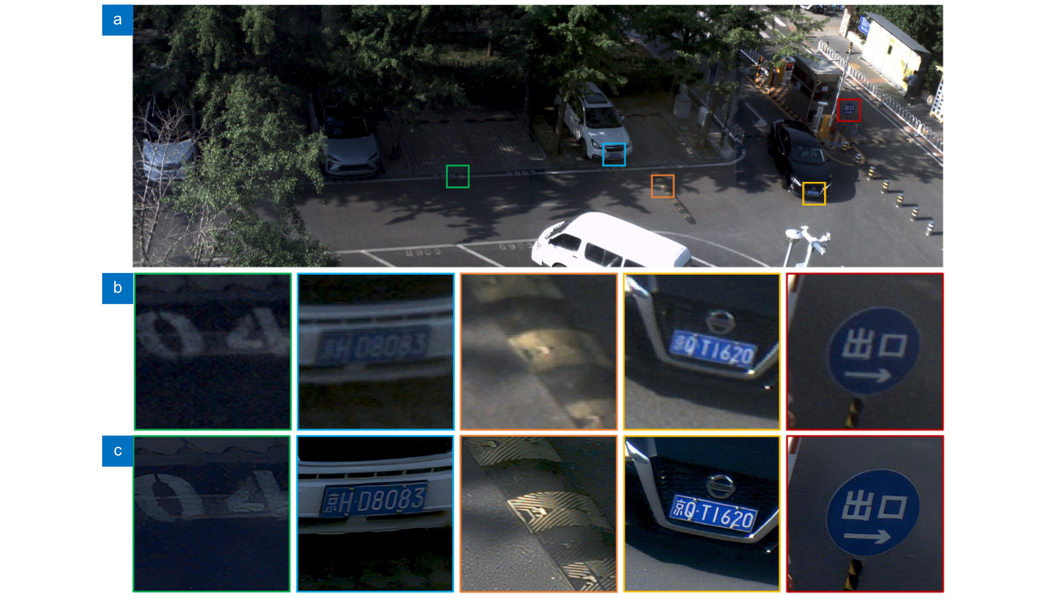
In order to test the imaging performance of the sparse CEC based on dual-end collaborative optimization framework in more general real-world scenarios, it is used to capture images of a parking lot scene. After pixel mapping and white balance and image brightness correction, we successfully complete the stitching of four sub field of view images, forming a large field of view image of the scene, as shown in Fig. 4(a). We enlarge and compare some key areas, especially those containing abundant semantic and texture information, to verify the effectiveness of high-resolution reconstruction, as shown in Fig. 4(b, c).
![Figure 4. Imaging and high-fidelity reconstruction results for real scenes. (a) Large field of view image captured by the proposed sparse CEC. (b) Local magnification of the large field of view image. (c) Reconstructed high resolution images through the dual-end collaborative zoom and optimization.]() Imaging and high-fidelity reconstruction results for real scenes. (a) Large field of view image captured by the proposed sparse CEC. (b) Local magnification of the large field of view image. (c) Reconstructed high resolution images through the dual-end collaborative zoom and optimization.
Imaging and high-fidelity reconstruction results for real scenes. (a) Large field of view image captured by the proposed sparse CEC. (b) Local magnification of the large field of view image. (c) Reconstructed high resolution images through the dual-end collaborative zoom and optimization.It can be seen that after dual-end collaborative zoom and optimization, the texts on the landmark, license plates, and road sign becomes clearer, and the texture information of the speed bump is also successfully enhanced. Although humans can mentally supplement information based on life experience, it is difficult for machines to do so. The proposed strategy successfully enhances the effective information of key target images in real scenes by combining optical and computational methods, demonstrating significant practical application value in machine vision.
Imaging performance for targets at different distances
When capturing targets at different distances, the environmental interference factors in the imaging may change, which brings challenges to the robustness and generalization of the method. To further test the imaging performance when dealing with different imaging conditions, the sparse CEC is used to capture an urban scene, which contains targets at different distances.
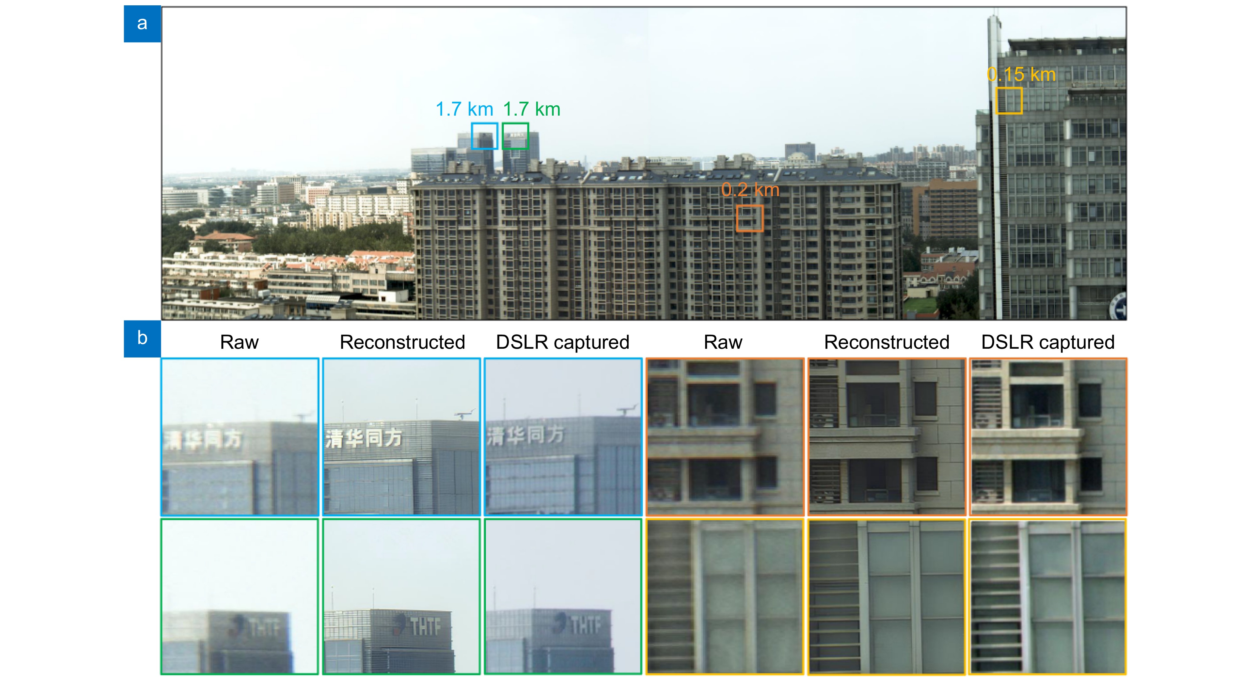
Similar to the previous experimental steps, we stitch the sub field of view images captured by four sub-cameras to obtain a large field of view image of the scene, as shown in Fig. 5(a). Then we compare the locally magnified images of targets at different distances before and after dual-end collaborative zoom and optimization, including buildings located approximately 0.15 km and 0.2 km away, as well as signs located approximately 1.7 km away from the sparse CEC. It can be seen that the proposed strategy is still effective, bringing obvious improvement of image resolution and significant suppression of noise and blur, as shown in Fig. 5(b). This is the result of the combination of fast optical zoom which effectively extends the captured information frequency domain, and disturbed degradation model which helps demodulate and enhance effective information.
![Figure 5. Imaging and high resolution reconstruction results of targets at different distances. (a) Large field of view image captured by the proposed sparse CEC. (b) Comparison between the raw images, reconstructed images through the dual-end collaborative zoom and optimization, and the images captured by a DSLR camera.]() Imaging and high resolution reconstruction results of targets at different distances. (a) Large field of view image captured by the proposed sparse CEC. (b) Comparison between the raw images, reconstructed images through the dual-end collaborative zoom and optimization, and the images captured by a DSLR camera.
Imaging and high resolution reconstruction results of targets at different distances. (a) Large field of view image captured by the proposed sparse CEC. (b) Comparison between the raw images, reconstructed images through the dual-end collaborative zoom and optimization, and the images captured by a DSLR camera.Moreover, we also use a digital single lens reflex (DSLR) camera (Canon EOS 6D Mark II, with 26.2 million pixels) with a lens (RF24-105mm F4 L IS USM) to capture images of the targets under telephoto shooting status, for comparing the fidelity of high-resolution reconstruction of the images. Although the exposure time of the DSLR camera is set to be the same as the proposed CEC, due to differences in ambient lighting conditions and spectral responsiveness of image sensors, there are some differences in the brightness and visual contrast of the images. Nevertheless, the feature information of the targets remains basically consistent, and the reconstructed images show better denoising and anti-ghosting effects. This means that the proposed sparse CEC operating with dual-end collaborative optimization framework achieves comparable imaging quality with a data transmission bandwidth requirement around four times lower than the DSLR camera.
Dynamic imaging and precise recognition of targets of interest
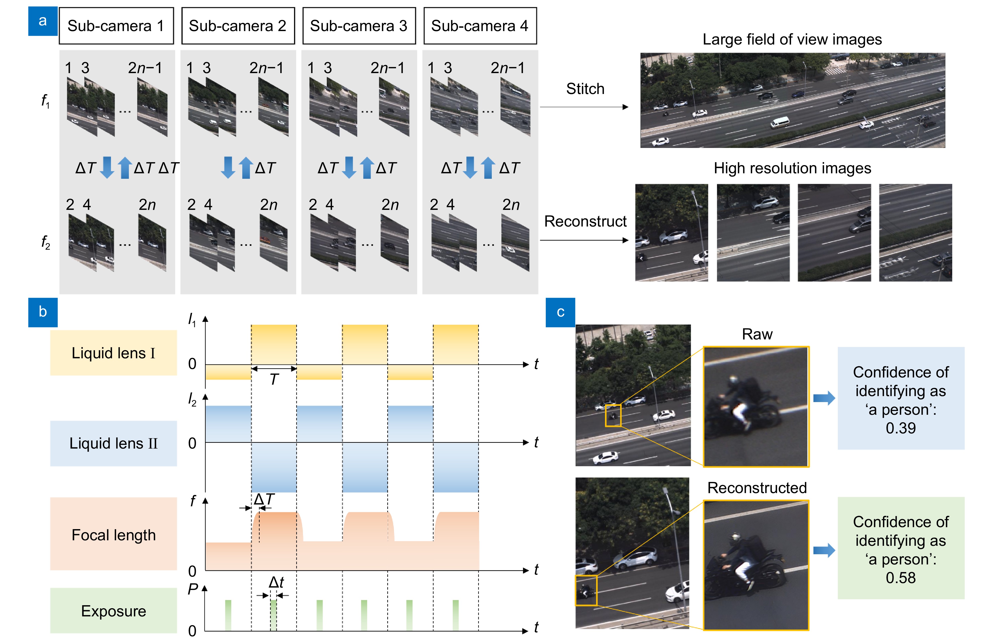
To demonstrate the fast imaging speed characteristics, we construct a dynamic imaging pipeline for the camera and select a highway as the imaging test scenario, as shown in Fig. 6(a). Although each sub-camera can be independently controlled and selectively trigger zoom imaging, to test the critical situation of dynamic imaging, the zoom imaging time duty cycle is set to 50%. That is to say, the imaging focal length state of each sub-camera is controlled by a square wave signal with a duty cycle of 50%, and dual focus images are alternately captured, as shown in Fig. 6(b).
![Figure 6. Dynamic imaging pipeline and precise recognition of targets of interest. (a) Dynamic imaging pipeline of the proposed sparse CEC. (b) Timing control of zoom and image acquisition. (c) Recognition results of targets of interest before and after dual-end collaborative zoom and optimization.]() Dynamic imaging pipeline and precise recognition of targets of interest. (a) Dynamic imaging pipeline of the proposed sparse CEC. (b) Timing control of zoom and image acquisition. (c) Recognition results of targets of interest before and after dual-end collaborative zoom and optimization.
Dynamic imaging pipeline and precise recognition of targets of interest. (a) Dynamic imaging pipeline of the proposed sparse CEC. (b) Timing control of zoom and image acquisition. (c) Recognition results of targets of interest before and after dual-end collaborative zoom and optimization.Initialization processing is performed at the beginning of the operation, during which the white balance coefficient, gain coefficient, and internal and external parameters of the sub-cameras are pre-calibrated. During the first duration T, the focal lengths of the sub-cameras are synchronously adjusted to 18 mm, and images captured by the four sub-cameras can be directly stitched through pixel mapping to form a large field of view image. Then, during the second duration T, the focal lengths of the sub-cameras are synchronously adjusted to 36 mm, and images captured by the four sub-cameras can be stored, then reconstructed through the DDMDSR-Net in the background or executed other processing. Due to lower bandwidth requirements, the storage can be completed in real-time on a single computer. The acquisition speed of dynamic dual focus images is mainly determined by the zoom response time of the liquid lenses and the exposure time of the image sensors. During the operation, it is found that although the focal length of the liquid lens can be basically achieved within 5 ms after the zoom signal is triggered, it is best to delay the start time of exposure appropriately due to the continuous slight oscillation of the liquid surface, which can help to avoid image integration blur. The supportable acquisition period of dual focus images is limited to:
2T⩾2(ΔT+Δt+ϵ), (3) where ∆T is the zoom response time of the liquid lenses considering the duration of slight oscillation, ∆t is the exposure time, and ε is the time delay caused by synchronization error of the sub-cameras or other interference factors. In the demonstration experiment (Supplementary Media 1), ∆T is set to 20 ms, ∆t is set to 5 ms, and ε is set to 13 ms, which means the acquisition frame rate of each focal length image can reach 13 fps and the time difference between obtaining images of the same target with two focal lengths does not exceed 38 ms, which is sufficient to deal with most dynamic scenes. It should be noted that by optimizing the synchronization triggering mechanism, ε can theoretically be further compressed and faster dynamic dual focus imaging speed can be achieved. The maximum acquisition frame rate of each focal length image can reach around 20 fps, which is almost impossible to achieve by using traditional mechanical zoom mode.
In addition, we also demonstrate the potential applications of the sparse CEC based on dual-end collaborative optimization framework in target search and precise recognition. When used for urban traffic monitoring, the sparse CEC can achieve real-time acquisition of large field of view images, which means that it has efficient search capabilities. Meanwhile, for potential targets of interest, precise recognition can be achieved through dual-end collaborative zoom and optimization. For example, when using YOLOV5 algorithm40 for detection for the motorcycle rider in the scene, as shown in Fig. 6(c), the confidence of identifying the target as 'a person' before dual-end collaborative zoom and optimization is only 0.39, indicating a risk of misjudgment. After dual-end collaborative zoom and optimization, the confidence of identifying the target as 'a person' reaches 0.58, basically achieving accurate recognition. The reasons for not achieving higher confidence may include the presence of motion blur of dynamic targets. It is possible to deal with this issue by further reducing the image exposure time and optimizing the imaging frame rate, or using additional algorithms for motion blur suppression. In addition, when the imaging frame rate is high enough, the display frame rate of the display device also needs special attention to avoid possible information loss41 in interactive usage scenarios with user participation.
In summary, a fast-zoom and high-resolution sparse CEC based on dual-end collaborative optimization framework is developed in this paper, which combines the advantages of liquid lens technology and computational imaging technology. By designing the sub-cameras based on liquid lenses, effective extension of captured information frequency domain for the targets of interest can be achieved through fast optical zoom. And through the designed DDMDSR-Net, effective information demodulation and resolution enhancement can be achieved with high robustness and fidelity. The designed network also shows significant advantages compared to other methods, including more effective reconstruction method based on the proposed disturbed degradation model, and stronger data learning ability (Supplementary information Section 5).
We not only present the operation process and effectiveness of the dual-end collaborative optimization framework through resolution testing experiments, but also demonstrate the ability to deal with complex image degradation issues through actual imaging experiments in various real scenarios. The successful implementation of the results is attributed to the combination of the physical driving optical zoom method based on liquid lenses and the computational demodulation method based on the proposed DDMDSR-Net. The liquid lens based optical zoom method can fast expand the frequency domain of obtainable information when capturing images of the target area of interest, and the DDMDSR-Net can extract and enhance effective information with high-robustness and high-fidelity within the frequency domain of obtainable information in actual imaging scenarios with multiple interferences. The designed compound eye camera has strong dynamic imaging capability, and can effectively complete the tasks of efficient search and accurate recognition of dynamic targets. Moreover, we believe that our proposed dual-end collaborative optimization framework can help achieve sparsity in compound-eye array cameras and significantly reduce the cost of use. For example, compared to the classic Aqueti Mantis series compound-eye array camera consisting of 18 sub cameras with 107 megapixels totally42, our designed CEC consisting of 4 sub cameras can achieve comparable field of view and resolution during real-world imaging, and can reduce data transmission bandwidth and weight by about an order of magnitude, which indicates the potential to be used on mobile platforms.
The proposed CEC has the potential for further improvement through some ways, such as using liquid lenses with larger zoom range43, increasing the number of liquid lenses used in each sub-camera, optimizing the system design, or using some advanced photoelectric devices44 to further enhance the zoom capability of the CEC, achieving higher resolution. However, the trade-off between zoom imaging capability and hardware cost needs to be considered. Besides, some advanced optical and digital methods can also be deployed to improve imaging performance, including further suppressing image artifacts caused by color dispersion45,46 and reducing image stitching gaps47. With further hardware optimization and on-chip acceleration algorithm design, the proposed sparse CEC can provide solutions for many practical application tasks.
Conclusions
In conclusion, a fast-zoom and high-resolution sparse CEC based on dual-end collaborative optimization framework is proposed, which provides a cost-effective way to break through the trade-off among the field of view, resolution, and imaging speed. The proposed sparse CEC enables large-field-of-view imaging in real time, can achieve fast zoom imaging with a response time of 5 ms, and can successfully enhance the angular resolution from 71.6" to 26.0" through dual-end collaborative optimization. This work represents a significant advancement combining new optical devices and design methods with advanced computational imaging methods, which is effective to improve imaging performance while maintaining a low demand of optical hardware complexity and data transmission bandwidth. The proposed CEC has important application value in fields such as geodesy, search and track, urban traffic monitoring.
Methods
Structure of the DDMDSR-Net
The proposed DDMDSR-Net uses SWinIR48 as the fundamental model, and a channel attention mechanism is introduced to the model to deeply fuse the extracted feature maps. In the deep feature extraction module of the DDMDSR-Net, the RSTB module is a residual module with Swin Transformer layers (STLs) and convolution layer, where STL is the core of RSTB. By using the shift window mechanism of STL, the input tensor is divided into multiple non-overlapping windows, and the local attention of each window is calculated separately, which has less computational resource consumption and faster speed than traditional Vision Transformer (ViT). And CAB can perform channel based wise weighted allocation on the obtained feature maps, activate and amplify useful features, and suppress useless features.
Training details
During the process of network training, a composite loss function is set as
L=αLL1+βLGAN+ηLPE, (4) where LL1, LGAN and LPE are the naive L1 pixel loss, GAN loss and perceptual loss49, respectively, α, β and η are the corresponding weights, respectively, which are specifically set as 1, 0.1 and 1 in the experiment. For the GAN loss, we use the PatchGAN model50 as the discriminator network, which is trained jointly with the generator network to facilitate the recovery of high-frequency features. For the perceptual loss, we use the VGG19 network to extract image features, which encourages the network to generate images with more realistic details and better visual effects.
The Flickr2K and part of the OST datasets are used as the training set containing a total of 6500 images. We finetune the pretrained SwinIR model in realword super-resolution task to accelerate the training process. In the training phase, the images are cropped into a set of small patches with a size of 256×256×3. The learning rate and batch size are set to 1×10⁻⁶ and 16 respectively. We run a total of 300 K iterations with 2 NVIDIA 3090 GPUs, and get the final training weights for testing.
Acknowledgements
We are grateful for financial supports from National Natural Science Foundation of China (Grant Nos. U23A20368 and 62175006) and Academic Excellence Foundation of BUAA for PhD Students. The authors also thank Prof. Di Wang from Beihang University for his help in polishing the manuscript.
Competing interests
The authors declare no competing financial interests.
-
References
[1] Zhang YL, Song XF, Xie JC et al. Large depth-of-field ultra-compact microscope by progressive optimization and deep learning. Nat Commun 14, 4118 (2023). DOI: 10.1038/s41467-023-39860-0[2] Xu X, Luo Q, Wang JX et al. Large-field objective lens for multi-wavelength microscopy at mesoscale and submicron resolution. Opto-Electron Adv 7, 230212 (2024). DOI: 10.29026/oea.2024.230212[3] Zhang YL, Wang MR, Zhu QY et al. Long-term mesoscale imaging of 3D intercellular dynamics across a mammalian organ. Cell 187, 6104–6122.e25 (2024). DOI: 10.1016/j.cell.2024.08.026[4] Zheng Y, Wang X, Jiang Z et al. Adaptive multiscale microscope with fast zooming, extended working distance, and large field of view. Light Adv Manuf 5, 62–74 (2024).[5] Xing Y, Lin XY, Zhang LB et al. Integral imaging-based tabletop light field 3D display with large viewing angle. Opto-Electron Adv 6, 220178 (2023). DOI: 10.29026/oea.2023.220178[6] Lee YH, Zhan T, Wu ST. Enhancing the resolution of a near-eye display with a Pancharatnam-Berry phase deflector. Opt Lett 42, 4732–4735 (2017). DOI: 10.1364/OL.42.004732View full references list -
Cited by
Periodical cited type(0)
Other cited types(6)
-
Author Information
-
Supplementary Information
TitleActions -
Copyright
Open Access. © The Author(s). This article is licensed under a Creative Commons Attribution 4.0 International License. To view a copy of this license, visit http://creativecommons.org/licenses/by/4.0/. -
About this Article
Cite this Article
Zheng Y, Zhang HR, Li XW et al. Fast-zoom and high-resolution sparse compound-eye camera based on dual-end collaborative optimization. Opto-Electron Adv 8, 240285 (2025). DOI: 10.29026/oea.2025.240285Download CitationArticle History
- Received Date December 01, 2024
- Accepted Date March 09, 2025
- Available Online April 27, 2025
- Published Date June 18, 2025
Article Metrics
Article Views(1251) PDF Downloads(158)
 OE Journals Group

Focuses on the advances of the cutting edge innovations of optics, photonics and optoelectronics
JCR Impact Factor: 22.4
CiteScore: 26.8
Open Access