-
Abstract
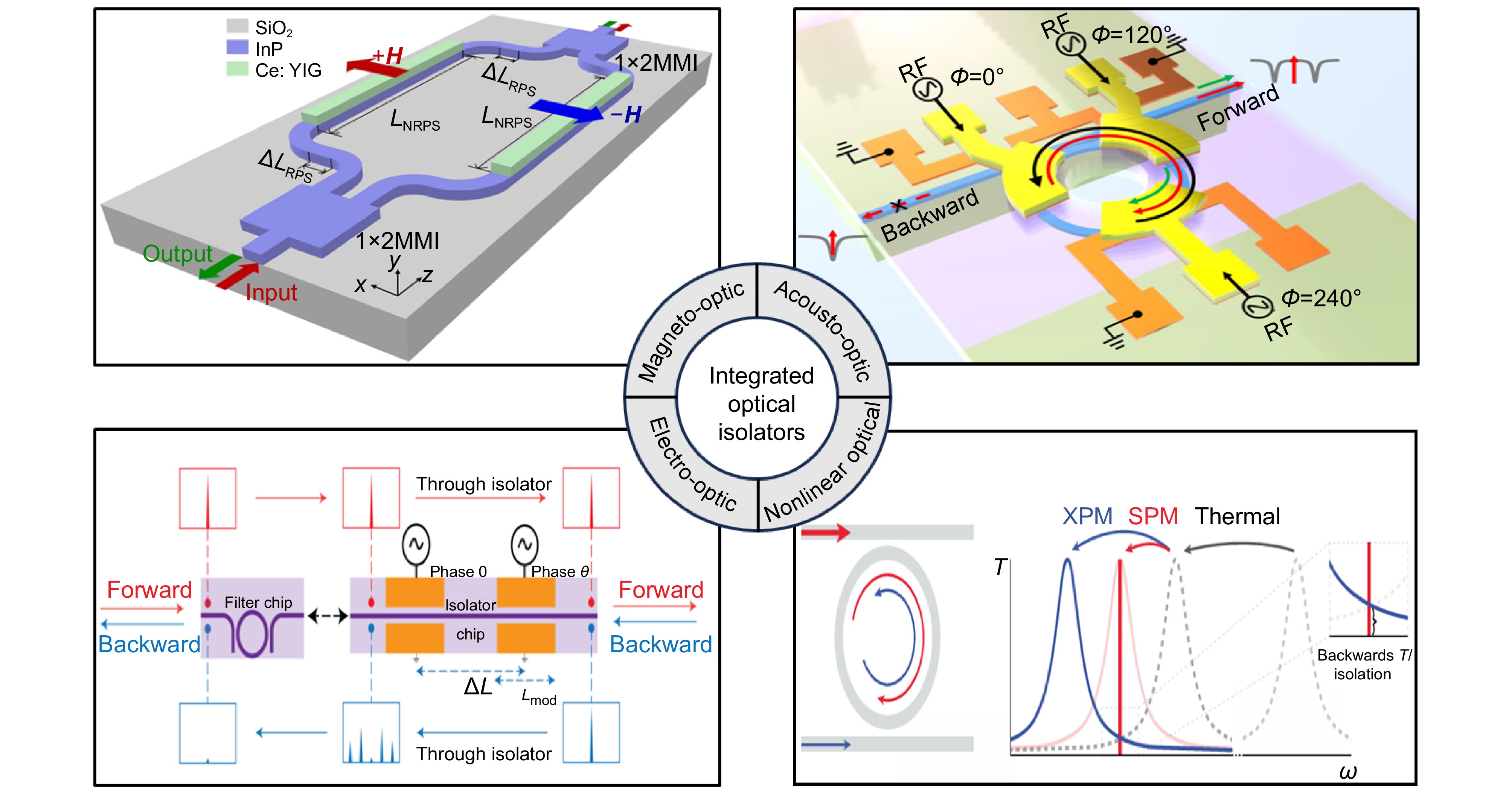
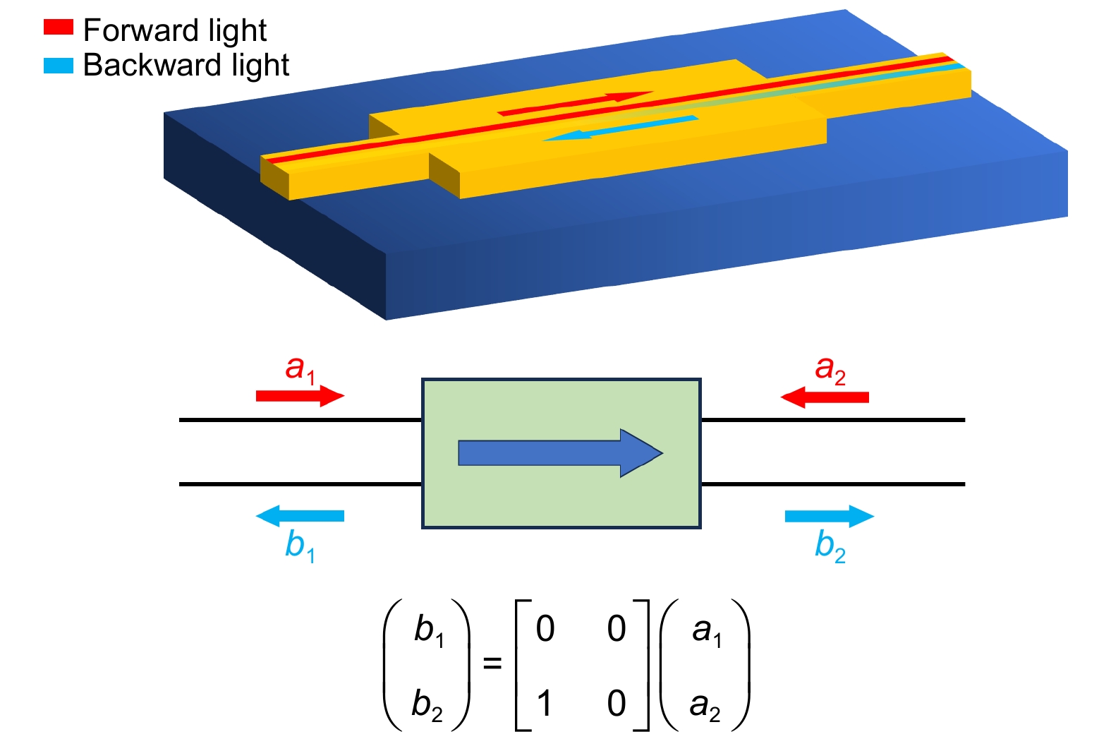
As the information age progresses rapidly, the demand for silicon photonic integrated circuits in optical communication, quantum precision measurement, artificial intelligence optical computing, and microwave photonics continues to grow. As an essential component of silicon photonic integrated circuits, optical isolators effectively prevent the backpropagation of optical signals, ensuring system stability and reliability. They are widely used in key technologies such as optical fiber communication, quantum communication, and laser systems. This paper reviews the research progress on on-chip integrated optical isolators, focusing on different implementation methods based on magneto-optic, acousto-optic, electro-optic, and nonlinear optical effects, discussing the advantages and challenges associated with each type. Finally, the paper explores future development directions and potential applications.
Keywords
-

-
References
[1] Pérez D, Gasulla I, Crudgington L, et al. Multipurpose silicon photonics signal processor core[J]. Nat Commun, 2017, 8(1): 636.
DOI: 10.1038/s41467-017-00714-1[2] 恽斌峰, 胡国华, 史上清, 等. 微波光子集成芯片研究进展(特邀)[J]. 光学学报, 2024, 44(15): 1513029.
DOI: 10.3788/AOS240983Yun B F, Hu G H, Shi S Q, et al. Research progress in integrated microwave photonic chips (Invited)[J]. Acta Opt Sin, 2024, 44(15): 1513029.
DOI: 10.3788/AOS240983[3] Bogaerts W, Pérez D, Capmany J, et al. Programmable photonic circuits[J]. Nature, 2020, 586(7828): 207−216.
DOI: 10.1038/s41586-020-2764-0[4] Chi Y L, Yu Y, Gong Q H, et al. High-dimensional quantum information processing on programmable integrated photonic chips[J]. Sci China Information Sci, 2023, 66(8): 180501.
DOI: 10.1007/s11432-022-3602-0[5] Jalas D, Petrov A, Eich M, et al. What is—and what is not—an optical isolator[J]. Nat Photonics, 2013, 7(8): 579−582.
DOI: 10.1038/nphoton.2013.185[6] 张子健, 严巍, 秦俊, 等. 集成非互易光学器件(特邀)[J]. 光学学报, 2024, 44(15): 1513020.
DOI: 10.3788/AOS241073Zhang Z J, Yan W, Qin J, et al. Integrated nonreciprocal photonic devices (Invited)[J]. Acta Opt Sin, 2024, 44(15): 1513020.
DOI: 10.3788/AOS241073[7] Shoji Y, Mizumoto T. Magneto-optical non-reciprocal devices in silicon photonics[J]. Sci Technol Adv Mater, 2014, 15(1): 014602.
DOI: 10.1088/1468-6996/15/1/014602[8] Bi L, Hu J J, Jiang P, et al. On-chip optical isolation in monolithically integrated non-reciprocal optical resonators[J]. Nat Photonics, 2011, 5(12): 758−762.
DOI: 10.1038/nphoton.2011.270[9] Yang J S, Roh J W, Ok S H, et al. An integrated optical waveguide isolator based on multimode interference by wafer direct bonding[J]. IEEE Trans Magn, 2005, 41(10): 3520−3522.
DOI: 10.1109/TMAG.2005.854960[10] Sohn D B, Örsel O E, Bahl G. Electrically driven optical isolation through phonon-mediated photonic Autler–Townes splitting[J]. Nat Photonics, 2021, 15(11): 822−827.
DOI: 10.1038/s41566-021-00884-x[11] Kittlaus E A, Jones W M, Rakich P T, et al. Electrically driven acousto-optics and broadband non-reciprocity in silicon photonics[J]. Nat Photonics, 2021, 15(1): 43−52.
DOI: 10.1038/s41566-020-00711-9[12] Tian H, Liu J Q, Siddharth A, et al. Magnetic-free silicon nitride integrated optical isolator[J]. Nat Photonics, 2021, 15(11): 828−836.
DOI: 10.1038/s41566-021-00882-z[13] Dong P. Travelling-wave Mach-Zehnder modulators functioning as optical isolators[J]. Opt Express, 2015, 23(8): 10498−10505.
DOI: 10.1364/OE.23.010498[14] Yu M J, Cheng R, Reimer C, et al. Integrated electro-optic isolator on thin-film lithium niobate[J]. Nat Photonics, 2023, 17(8): 666−671.
DOI: 10.1038/s41566-023-01227-8[15] Shah M, Briggs I, Chen P K, et al. Visible-telecom tunable dual-band optical isolator based on dynamic modulation in thin-film lithium niobate[J]. Opt Lett, 2023, 48(8): 1978−1981.
DOI: 10.1364/OL.482635[16] Saha K, Okawachi Y, Kuzucu O, et al. Chip-scale broadband optical isolation via Bragg scattering four-wave mixing[C]//CLEO: 2013, 2013: 1–2. https://doi.org/10.1364/CLEO_QELS.2013.QF1D.2.
[17] Del Bino L, Silver J M, Zhao X, et al. Isolators and circulators based on Kerr nonreciprocity in microresonators[C]//2017 Conference on Lasers and Electro-Optics Europe & European Quantum Electronics Conference, 2017: 1. https://doi.org/10.1109/CLEOE-EQEC.2017.8086519.
[18] White A D, Ahn G H, van Gasse K, et al. Integrated passive nonlinear optical isolators[J]. Nat Photonics, 2023, 17(2): 143−149.
DOI: 10.1038/s41566-022-01110-y[19] Herrmann J F, Ansari V, Wang J H, et al. Mirror symmetric on-chip frequency circulation of light[J]. Nat Photonics, 2022, 16(8): 603−608.
DOI: 10.1038/s41566-022-01026-7[20] Abdelsalam K, Li T F, Khurgin J B, et al. Linear isolators using wavelength conversion[J]. Optica, 2020, 7(3): 209−213.
DOI: 10.1364/OPTICA.385639[21] Chen W T, Liu L, Zhao J, et al. On-chip broadband, compact TM mode Mach–Zehnder optical isolator based on InP-on-insulator platforms[J]. Nanomaterials, 2024, 14(8): 709.
DOI: 10.3390/nano14080709[22] Potton R J. Reciprocity in optics[J]. Rep Prog Phys, 2004, 67(5): 717−754.
DOI: 10.1088/0034-4885/67/5/R03[23] Adam J D, Davis L E, Dionne G F, et al. Ferrite devices and materials[J]. IEEE Trans Microwave Theory Tech, 2002, 50(3): 721−737.
DOI: 10.1109/22.989957[24] Dötsch H, Bahlmann N, Zhuromskyy O, et al. Applications of magneto-optical waveguides in integrated optics: review[J]. J Opt Soc Am B, 2005, 22(1): 240−253.
DOI: 10.1364/JOSAB.22.000240[25] Karki D, Stenger V, Pollick A, et al. Broadband bias-magnet-free on-chip optical isolators with integrated thin film polarizers[J]. J Lightwave Technol, 2020, 38(4): 827−833.
DOI: 10.1109/JLT.2019.2949377[26] Yan W, Yang Y C, Yang W H, et al. On-chip nonreciprocal photonic devices based on hybrid integration of magneto-optical garnet thin films on silicon[J]. IEEE J Sel Top Quantum Electron, 2022, 28(3): 6100515.
DOI: 10.1109/JSTQE.2021.3133445[27] Liang X, Xie J L, Deng L J, et al. First principles calculation on the magnetic, optical properties and oxygen vacancy effect of Ce xY3− xFe5O12[J]. Appl Phys Lett, 2015, 106(5): 052401.
DOI: 10.1063/1.4907413[28] Zaki A M, Blythe H J, Heald S M, et al. Growth of high quality yttrium iron garnet films using standard pulsed laser deposition technique[J]. J Magn Magn Mater, 2018, 453: 254−257.
DOI: 10.1016/j.jmmm.2017.11.054[29] Gomi M, Furuyama H, Abe M. Strong magneto-optical enhancement in highly Ce-substituted iron garnet films prepared by sputtering[J]. J Appl Phys, 1991, 70(11): 7065−7067.
DOI: 10.1063/1.349786[30] Mizumoto T, Naito Y. Nonreciprocal propagation characteristics of YIG thin film[J]. IEEE Trans Microwave Theory Tech, 1982, 30(6): 922−925.
DOI: 10.1109/TMTT.1982.1131173[31] Shoji Y, Fujie A, Mizumoto T. Silicon waveguide optical isolator operating for TE mode input light[J]. IEEE J Sel Top Quantum Electron, 2016, 22(6): 4403307.
DOI: 10.1109/JSTQE.2016.2574678[32] Zhang Y, Du Q Y, Wang C T, et al. Monolithic integration of broadband optical isolators for polarization-diverse silicon photonics[J]. Optica, 2019, 6(4): 473−478.
DOI: 10.1364/OPTICA.6.000473[33] Huang D N, Pintus P, Zhang C, et al. Electrically driven and thermally tunable integrated optical isolators for silicon photonics[J]. IEEE J Sel Top Quantum Electron, 2016, 22(6): 4403408.
DOI: 10.1109/JSTQE.2016.2588778[34] Du Q Y, Wang C T, Zhang Y F, et al. Monolithic on-chip magneto-optical isolator with 3 dB insertion loss and 40 dB isolation ratio[J]. ACS Photonics, 2018, 5(12): 5010−5016.
DOI: 10.1021/acsphotonics.8b01257[35] Shui K Y, Nie L X, Zhang Y, et al. Design of a compact waveguide optical isolator based on multimode interferometers using magneto-optical oxide thin films grown on silicon-on-insulator substrates[J]. Opt Express, 2016, 24(12): 12856−12867.
DOI: 10.1364/OE.24.012856[36] Yamaguchi R, Shoji Y, Mizumoto T. Low-loss waveguide optical isolator with tapered mode converter and magneto-optical phase shifter for TE mode input[J]. Opt Express, 2018, 26(16): 21271−21278.
DOI: 10.1364/OE.26.021271[37] Auracher F, Witte H H. A new design for an integrated optical isolator[J]. Opt Commun, 1975, 13(4): 435−438.
DOI: 10.1016/0030-4018(75)90140-6[38] Ghosh S, Keyvavinia S, Van Roy W, et al. Ce: YIG/Silicon-on-Insulator waveguide optical isolator realized by adhesive bonding[J]. Opt Express, 2012, 20(2): 1839−1848.
DOI: 10.1364/OE.20.001839[39] Ghosh S, Keyvaninia S, Shirato Y, et al. Optical isolator for TE polarized light realized by adhesive bonding of Ce: YIG on silicon-on-insulator waveguide circuits[J]. IEEE Photonics J, 2013, 5(3): 6601108.
DOI: 10.1109/JPHOT.2013.2264275[40] Yan W, Yang Y C, Liu S Y, et al. Waveguide-integrated high-performance magneto-optical isolators and circulators on silicon nitride platforms[J]. Optica, 2020, 7(11): 1555−1562.
DOI: 10.1364/OPTICA.408458[41] Tien M C, Mizumoto T, Pintus P, et al. Silicon ring isolators with bonded nonreciprocal magneto-optic garnets[J]. Opt Express, 2011, 19(12): 11740−11745.
DOI: 10.1364/OE.19.011740[42] Huang D N, Pintus P, Bowers J E. Towards heterogeneous integration of optical isolators and circulators with lasers on silicon [Invited][J]. Opt Mater Express, 2018, 8(9): 2471−2483.
DOI: 10.1364/OME.8.002471[43] Pintus P, Huang D N, Zhang C, et al. Microring-based optical isolator and circulator with integrated electromagnet for silicon photonics[J]. J Lightwave Technol, 2017, 35(8): 1429−1437.
DOI: 10.1109/JLT.2016.2644626[44] Zhuromskyy O, Lohmeyer M, Bahlmann N, et al. Analysis of nonreciprocal light propagation in multimode imaging devices[J]. Opt Quantum Electron, 2000, 32(6): 885−897.
DOI: 10.1023/A:1007078814985[45] Furuya K, Nemoto T, Kato K, et al. Athermal operation of a waveguide optical isolator based on canceling phase deviations in a Mach–Zehnder interferometer[J]. J Lightwave Technol, 2016, 34(8): 1699−1705.
DOI: 10.1109/JLT.2015.2505538[46] Yokoi H, Mizumoto T, Shinjo N, et al. Demonstration of an optical isolator with a semiconductor guiding layer that was obtained by use of a nonreciprocal phase shift[J]. Appl Opt, 2000, 39(33): 6158−6164.
DOI: 10.1364/AO.39.006158[47] Yokoi H, Shoji Y, Shin E, et al. Interferometric optical isolator employing a nonreciprocal phase shift operated in a unidirectional magnetic field[J]. Appl Opt, 2004, 43(24): 4745−4752.
DOI: 10.1364/AO.43.004745[48] Shoji Y, Mizumoto T, Yokoi H, et al. Magneto-optical isolator with silicon waveguides fabricated by direct bonding[J]. Appl Phys Lett, 2008, 92(7): 071117.
DOI: 10.1063/1.2884855[49] Ishida E, Miura K, Shoji Y, et al. Amorphous-Si waveguide on a garnet magneto-optical isolator with a TE mode nonreciprocal phase shift[J]. Opt Express, 2017, 25(1): 452−462.
DOI: 10.1364/OE.25.000452[50] Huang D N, Pintus P, Shoji Y, et al. Integrated broadband Ce: YIG/Si Mach–Zehnder optical isolators with over 100 nm tuning range[J]. Opt Lett, 2017, 42(23): 4901−4904.
DOI: 10.1364/OL.42.004901[51] Huang D N, Pintus P, Zhang C, et al. Dynamically reconfigurable integrated optical circulators[J]. Optica, 2017, 4(1): 23−30.
DOI: 10.1364/OPTICA.4.000023[52] Liu S Y, Shoji Y, Mizumoto T. Mode-evolution-based TE mode magneto-optical isolator using asymmetric adiabatic tapered waveguides[J]. Opt Express, 2021, 29(15): 22838−22846.
DOI: 10.1364/OE.427914[53] Liu L, Chen W T, Zhao J, et al. Two structural designs of broadband, low-loss, and compact TM magneto-optical isolator based on GaAs-on-insulator[J]. Nanomaterials, 2024, 14(5): 400.
DOI: 10.3390/nano14050400[54] Tadesse S A, Li M. Sub-optical wavelength acoustic wave modulation of integrated photonic resonators at microwave frequencies[J]. Nat Commun, 2014, 5(1): 5402.
DOI: 10.1038/ncomms6402[55] Liu J Q, Tian H, Lucas E, et al. Monolithic piezoelectric control of soliton microcombs[J]. Nature, 2020, 583(7816): 385−390.
DOI: 10.1038/s41586-020-2465-8[56] Tadesse S A, Li H, Liu Q Y, et al. Acousto-optic modulation of a photonic crystal nanocavity with Lamb waves in microwave K band[J]. Appl Phys Lett, 2015, 107(20): 201113.
DOI: 10.1063/1.4935981[57] Luo Z F, Zhang A X, Huang W X, et al. Aluminum nitride thin film based reconfigurable integrated photonic devices[J]. IEEE J Sel Top Quantum Electron, 2023, 29(3): 9300119.
DOI: 10.1109/JSTQE.2023.3245290[58] Shao L B, Yu M J, Maity S, et al. Microwave-to-optical conversion using lithium niobate thin-film acoustic resonators[J]. Optica, 2019, 6(12): 1498−1505.
DOI: 10.1364/OPTICA.6.001498[59] Sohn D B, Kim S, Bahl G. Time-reversal symmetry breaking with acoustic pumping of nanophotonic circuits[J]. Nat Photonics, 2018, 12(2): 91−97.
DOI: 10.1038/s41566-017-0075-2[60] Kuhn L, Heidrich P F, Lean E G. Optical guided wave mode conversion by an acoustic surface wave[J]. Appl Phys Lett, 1971, 19(10): 428−430.
DOI: 10.1063/1.1653758[61] Sohn D B, Bahl G. Direction reconfigurable nonreciprocal acousto-optic modulator on chip[J]. APL Photonics, 2019, 4(12): 126103.
DOI: 10.1063/1.5123497[62] Tian H, Liu J Q, Dong B, et al. Hybrid integrated photonics using bulk acoustic resonators[J]. Nat Commun, 2020, 11(1): 3073.
DOI: 10.1038/s41467-020-16812-6[63] Wang C, Zhang M, Chen X, et al. Integrated lithium niobate electro-optic modulators operating at CMOS-compatible voltages[J]. Nature, 2018, 562(7725): 101−104.
DOI: 10.1038/s41586-018-0551-y[64] Bhandare S, Ibrahim S K, Sandel D, et al. Novel nonmagnetic 30-dB traveling-wave single-sideband optical isolator integrated in III/V material[J]. IEEE J Sel Top Quantum Electron, 2005, 11(2): 417−421.
DOI: 10.1109/JSTQE.2005.845620[65] Dong P, Gui C C. Observation of nonreciprocal transmission in binary phase-shift keying modulation using traveling-wave Mach–Zehnder modulators[J]. Opt Lett, 2016, 41(12): 2723−2726.
DOI: 10.1364/OL.41.002723[66] Dostart N, Gevorgyan H, Onural D, et al. Optical isolation using microring modulators[J]. Opt Lett, 2021, 46(3): 460−463.
DOI: 10.1364/OL.408614[67] Del Bino L, Silver J M, Stebbings S L, et al. Symmetry breaking of counter-propagating light in a nonlinear resonator[J]. Sci Rep, 2017, 7(1): 43142.
DOI: 10.1038/srep43142[68] 程亚. 薄膜铌酸锂光电器件与超大规模光子集成(特邀)[J]. 中国激光, 2024, 51(1): 0119001.
DOI: 10.3788/CJL231256Cheng Y. Thin film lithium niobate electro-optic devices and ultralarge-scale photonic integration (Invited)[J]. Chin J Lasers, 2024, 51(1): 0119001.
DOI: 10.3788/CJL231256View full references list -
Author Information
-
Yang Zongqi, yang718@buaa.edu.cn On this SiteOn Google Scholar
- School of Electronics and Information Engineering, Beihang University, Beijing 100191, China
-
Li Wenxiu On this SiteOn Google Scholar
- School of Electronics and Information Engineering, Beihang University, Beijing 100191, China
-
Sun Xin On this SiteOn Google Scholar
- School of Electronics and Information Engineering, Beihang University, Beijing 100191, China
-
Huang Xinyao On this SiteOn Google Scholar
- School of Physics, Beihang University, Beijing 100191, China
-
Corresponding author: Yang He, yanghe@buaa.edu.cn On this SiteOn Google Scholar
- School of Instrumentation and Optoelectronic Engineering, Beihang University, Beijing 100191, China
-
Corresponding author: Zhang Hao, haozhang@buaa.edu.cn On this SiteOn Google Scholar
- School of Space and Earth Sciences, Beihang University, Beijing 100191, China
-
Huang Anping On this SiteOn Google Scholar
- School of Physics, Beihang University, Beijing 100191, China
-
Xiao Zhisong On this SiteOn Google Scholar
- School of Physics, Beihang University, Beijing 100191, China
- School of Instrumentation Science and Opto-electronics Engineering, Beijing Information Science and Technology University, Beijing 100192, China
-
-
Copyright
The copyright belongs to the Institute of Optics and Electronics, Chinese Academy of Sciences, but the article content can be freely downloaded from this website and used for free in academic and research work. -
About this Article
Cite this Article
Yang Zongqi, Li Wenxiu, Sun Xin, Huang Xinyao, Yang He, Zhang Hao, Huang Anping, Xiao Zhisong. Research progress on on-chip integrated optical isolators. Opto-Electronic Engineering 52, 240285 (2025). DOI: 10.12086/oee.2025.240285Yang Zongqi, Li Wenxiu, Sun Xin, Huang Xinyao, Yang He, Zhang Hao, Huang Anping, Xiao Zhisong. Research progress on on-chip integrated optical isolators. Opto-Electronic Engineering 52, 240285 (2025). DOI: 10.12086/oee.2025.240285Download CitationArticle History
- Received Date December 04, 2024
- Revised Date February 12, 2025
- Accepted Date February 12, 2025
- Published Date February 27, 2025
Article Metrics
Article Views(1338) PDF Downloads(190) -
Related Articles
-
![]() View in article Downloads
View in article Downloads -
![]() View in article Downloads
View in article Downloads -
![]() View in article Downloads
View in article Downloads -
![]() View in article Downloads
View in article Downloads -
![]() View in article Downloads
View in article Downloads -
![]() View in article Downloads
View in article Downloads -
![]() View in article Downloads
View in article Downloads -
![]() View in article Downloads
View in article Downloads -
![]() View in article Downloads
View in article Downloads -
![]() View in article Downloads
View in article Downloads -
![]() View in article Downloads
View in article Downloads -
![]() View in article Downloads
View in article Downloads -
![]() View in article Downloads
View in article Downloads -
![]() View in article Downloads
View in article Downloads -
![]() View in article Downloads
View in article Downloads -
![]() View in article Downloads
View in article Downloads
-
Device type Year Isolation ratio/dB Insertion loss/dB Isolation bandwidth/nm Polarization Platform Structure Ref MO-MZI 2000 4.90@1550 nm — — TM GaInAsP Waveguide [46] 2004 9.90@1550 nm 25.0 — TM HfO2 Waveguide [47] 2008 21.0@1559 nm 8.00 10@10 dB TM Si Waveguide [48] 2012 25.0@1495 nm 9.70 0.40@20 dB TM Si Waveguide [38] 2013 32.0@1540 nm 22.0 0.50@21 dB TE Si Waveguide [39] 2014 30.0@1548 nm 13.0 1.0@20 dB TM Si Waveguide [7] 2016 26.7@1553 nm 33.4 — TE Si Waveguide [31] 2017 17.9@1562 nm 10.0 2.0@10 dB TE a-Si:H Waveguide [49] 2017 29.0@1523 nm 9.00 18@20 dB TM Si Waveguide [50] 2019 30.0@1574 nm 5.00 9.0@10 dB TM Si Waveguide [32] 30.0@1588 nm 9.00 2.0@10 dB TE Si Waveguide 2020 32.0@1555 nm 2.30 4.0@20 dB TM Si3N4 Waveguide [40] 30.0@1558 nm 3.00 5.0@20 dB TE Si3N4 Waveguide 2024 50.0@1550 nm 0.687 72@30 dB TM InP Waveguide [21] MO-MR 2011 19.5@1541.6 nm 18.8 0.040@10 dB TM Si Ring [8] 2011 9.00@1550 nm — 0.040@5 dB TM Si Ring [41] 2016 32.0@1555 nm 2.30 0.60@20 dB TM Si Ring [33] 2017 11.0@1558 nm 9.70 0.16@5 dB TM Si Ring [51] 2017 32.0@1555 nm — 3.0@20 dB TM Si Ring [43] 2018 25.0@1550 nm 6.50 40@20 dB TE Si Ring [42] 2018 40.0@1560.1 nm 3.00 — TM GeSbSe Ring [34] 2019 20.0@1584.8 nm 11.5 — TE Si3N4 Ring [32] 2020 28.0@1570.3 nm 1.00 — TM Si3N4 Ring [40] MO-MMI 2005 2.9@1550 nm — — TM InGaAsP Waveguide [9] 2016 45@1550 nm 0.800 1.60@20 dB TM Si Waveguide [35] 2018 16@1561 nm 3.40 — TE Si Waveguide [36] 2021 15@1537.3 nm 5.00 2.00@10 dB TE Si Waveguide [52] 2024 45@1550 nm 2.59 53.5@35 dB TM GaAs Waveguide [53] 45@1550 nm 2.25 70.0@35 dB TM GaAs Waveguide View in article Downloads -
Device type Year Isolation ratio/dB Insertion loss/dB Isolation bandwidth/nm Polarization Platform Structure Ref AO 2018 15.0@1550 nm — 0.0088@3 dB TE AlN Ring [59] 2019 8.00@1540 nm — 0.0080@3 dB TE AlN Ring [61] 2021 12.0@1523.7 nm 0.6 0.80@16 dB TE Si Waveguide [11] 2021 39.3@1538 nm 1 0.0016@10 dB TE LiNbO3 Ring [10] 2021 10.0@1545.55 nm 0.1 0.0056@8 dB TE Si3N4 Ring [12] View in article Downloads -
Device type Year Isolation ratio/dB Insertion loss/dB Isolation bandwidth/nm Polarization Platform Structure Ref EO 2005 30.0@1550 nm 8.0 — — GaAs/
AlGaAsWaveguide [64] 2015 12.5@1500 nm 5.5 90.0@12.5 dB — LiNbO3 Waveguide [13] 2016 — 5.3 90.0@7 dB — LiNbO3 Waveguide [65] 2021 13@1556 nm 18 0.0160@3 dB — Si Ring [66] 2023 48.0@1553.2 nm 0.50 120@37 dB TE LiNbO3 Waveguide [14] 2023 15.0@1550 nm 0.50 100@10 dB TE LiNbO3 Waveguide [15] View in article Downloads -
Device type Year Isolation ratio/dB Insertion loss/dB Isolation bandwidth/nm Polarization Platform Structure Ref Kerr 2013 4.0@1582.3 nm — 8.00@4 dB — Si Waveguide [16] 2017 30@1550 nm 7.0 — — Fused silica Ring [17] 2022 23@1550 nm 4.6 — — Si3N4 Ring [18] 17@1550 nm 1.3 — — Si3N4 Ring χ(2) 2020 40@1570 nm 6.6 150@18 dB — LiNbO3 Waveguide [20] View in article Downloads
| [1] |
Pérez D, Gasulla I, Crudgington L, et al. Multipurpose silicon photonics signal processor core[J]. Nat Commun, 2017, 8(1): 636. DOI: 10.1038/s41467-017-00714-1 |
| [2] |
恽斌峰, 胡国华, 史上清, 等. 微波光子集成芯片研究进展(特邀)[J]. 光学学报, 2024, 44(15): 1513029. DOI: 10.3788/AOS240983Yun B F, Hu G H, Shi S Q, et al. Research progress in integrated microwave photonic chips (Invited)[J]. Acta Opt Sin, 2024, 44(15): 1513029. DOI: 10.3788/AOS240983 |
| [3] |
Bogaerts W, Pérez D, Capmany J, et al. Programmable photonic circuits[J]. Nature, 2020, 586(7828): 207−216. DOI: 10.1038/s41586-020-2764-0 |
| [4] |
Chi Y L, Yu Y, Gong Q H, et al. High-dimensional quantum information processing on programmable integrated photonic chips[J]. Sci China Information Sci, 2023, 66(8): 180501. DOI: 10.1007/s11432-022-3602-0 |
| [5] |
Jalas D, Petrov A, Eich M, et al. What is—and what is not—an optical isolator[J]. Nat Photonics, 2013, 7(8): 579−582. DOI: 10.1038/nphoton.2013.185 |
| [6] |
张子健, 严巍, 秦俊, 等. 集成非互易光学器件(特邀)[J]. 光学学报, 2024, 44(15): 1513020. DOI: 10.3788/AOS241073Zhang Z J, Yan W, Qin J, et al. Integrated nonreciprocal photonic devices (Invited)[J]. Acta Opt Sin, 2024, 44(15): 1513020. DOI: 10.3788/AOS241073 |
| [7] |
Shoji Y, Mizumoto T. Magneto-optical non-reciprocal devices in silicon photonics[J]. Sci Technol Adv Mater, 2014, 15(1): 014602. DOI: 10.1088/1468-6996/15/1/014602 |
| [8] |
Bi L, Hu J J, Jiang P, et al. On-chip optical isolation in monolithically integrated non-reciprocal optical resonators[J]. Nat Photonics, 2011, 5(12): 758−762. DOI: 10.1038/nphoton.2011.270 |
| [9] |
Yang J S, Roh J W, Ok S H, et al. An integrated optical waveguide isolator based on multimode interference by wafer direct bonding[J]. IEEE Trans Magn, 2005, 41(10): 3520−3522. DOI: 10.1109/TMAG.2005.854960 |
| [10] |
Sohn D B, Örsel O E, Bahl G. Electrically driven optical isolation through phonon-mediated photonic Autler–Townes splitting[J]. Nat Photonics, 2021, 15(11): 822−827. DOI: 10.1038/s41566-021-00884-x |
| [11] |
Kittlaus E A, Jones W M, Rakich P T, et al. Electrically driven acousto-optics and broadband non-reciprocity in silicon photonics[J]. Nat Photonics, 2021, 15(1): 43−52. DOI: 10.1038/s41566-020-00711-9 |
| [12] |
Tian H, Liu J Q, Siddharth A, et al. Magnetic-free silicon nitride integrated optical isolator[J]. Nat Photonics, 2021, 15(11): 828−836. DOI: 10.1038/s41566-021-00882-z |
| [13] |
Dong P. Travelling-wave Mach-Zehnder modulators functioning as optical isolators[J]. Opt Express, 2015, 23(8): 10498−10505. DOI: 10.1364/OE.23.010498 |
| [14] |
Yu M J, Cheng R, Reimer C, et al. Integrated electro-optic isolator on thin-film lithium niobate[J]. Nat Photonics, 2023, 17(8): 666−671. DOI: 10.1038/s41566-023-01227-8 |
| [15] |
Shah M, Briggs I, Chen P K, et al. Visible-telecom tunable dual-band optical isolator based on dynamic modulation in thin-film lithium niobate[J]. Opt Lett, 2023, 48(8): 1978−1981. DOI: 10.1364/OL.482635 |
| [16] |
Saha K, Okawachi Y, Kuzucu O, et al. Chip-scale broadband optical isolation via Bragg scattering four-wave mixing[C]//CLEO: 2013, 2013: 1–2. https://doi.org/10.1364/CLEO_QELS.2013.QF1D.2. |
| [17] |
Del Bino L, Silver J M, Zhao X, et al. Isolators and circulators based on Kerr nonreciprocity in microresonators[C]//2017 Conference on Lasers and Electro-Optics Europe & European Quantum Electronics Conference, 2017: 1. https://doi.org/10.1109/CLEOE-EQEC.2017.8086519. |
| [18] |
White A D, Ahn G H, van Gasse K, et al. Integrated passive nonlinear optical isolators[J]. Nat Photonics, 2023, 17(2): 143−149. DOI: 10.1038/s41566-022-01110-y |
| [19] |
Herrmann J F, Ansari V, Wang J H, et al. Mirror symmetric on-chip frequency circulation of light[J]. Nat Photonics, 2022, 16(8): 603−608. DOI: 10.1038/s41566-022-01026-7 |
| [20] |
Abdelsalam K, Li T F, Khurgin J B, et al. Linear isolators using wavelength conversion[J]. Optica, 2020, 7(3): 209−213. DOI: 10.1364/OPTICA.385639 |
| [21] |
Chen W T, Liu L, Zhao J, et al. On-chip broadband, compact TM mode Mach–Zehnder optical isolator based on InP-on-insulator platforms[J]. Nanomaterials, 2024, 14(8): 709. DOI: 10.3390/nano14080709 |
| [22] |
Potton R J. Reciprocity in optics[J]. Rep Prog Phys, 2004, 67(5): 717−754. DOI: 10.1088/0034-4885/67/5/R03 |
| [23] |
Adam J D, Davis L E, Dionne G F, et al. Ferrite devices and materials[J]. IEEE Trans Microwave Theory Tech, 2002, 50(3): 721−737. DOI: 10.1109/22.989957 |
| [24] |
Dötsch H, Bahlmann N, Zhuromskyy O, et al. Applications of magneto-optical waveguides in integrated optics: review[J]. J Opt Soc Am B, 2005, 22(1): 240−253. DOI: 10.1364/JOSAB.22.000240 |
| [25] |
Karki D, Stenger V, Pollick A, et al. Broadband bias-magnet-free on-chip optical isolators with integrated thin film polarizers[J]. J Lightwave Technol, 2020, 38(4): 827−833. DOI: 10.1109/JLT.2019.2949377 |
| [26] |
Yan W, Yang Y C, Yang W H, et al. On-chip nonreciprocal photonic devices based on hybrid integration of magneto-optical garnet thin films on silicon[J]. IEEE J Sel Top Quantum Electron, 2022, 28(3): 6100515. DOI: 10.1109/JSTQE.2021.3133445 |
| [27] |
Liang X, Xie J L, Deng L J, et al. First principles calculation on the magnetic, optical properties and oxygen vacancy effect of Ce xY3− xFe5O12[J]. Appl Phys Lett, 2015, 106(5): 052401. DOI: 10.1063/1.4907413 |
| [28] |
Zaki A M, Blythe H J, Heald S M, et al. Growth of high quality yttrium iron garnet films using standard pulsed laser deposition technique[J]. J Magn Magn Mater, 2018, 453: 254−257. DOI: 10.1016/j.jmmm.2017.11.054 |
| [29] |
Gomi M, Furuyama H, Abe M. Strong magneto-optical enhancement in highly Ce-substituted iron garnet films prepared by sputtering[J]. J Appl Phys, 1991, 70(11): 7065−7067. DOI: 10.1063/1.349786 |
| [30] |
Mizumoto T, Naito Y. Nonreciprocal propagation characteristics of YIG thin film[J]. IEEE Trans Microwave Theory Tech, 1982, 30(6): 922−925. DOI: 10.1109/TMTT.1982.1131173 |
| [31] |
Shoji Y, Fujie A, Mizumoto T. Silicon waveguide optical isolator operating for TE mode input light[J]. IEEE J Sel Top Quantum Electron, 2016, 22(6): 4403307. DOI: 10.1109/JSTQE.2016.2574678 |
| [32] |
Zhang Y, Du Q Y, Wang C T, et al. Monolithic integration of broadband optical isolators for polarization-diverse silicon photonics[J]. Optica, 2019, 6(4): 473−478. DOI: 10.1364/OPTICA.6.000473 |
| [33] |
Huang D N, Pintus P, Zhang C, et al. Electrically driven and thermally tunable integrated optical isolators for silicon photonics[J]. IEEE J Sel Top Quantum Electron, 2016, 22(6): 4403408. DOI: 10.1109/JSTQE.2016.2588778 |
| [34] |
Du Q Y, Wang C T, Zhang Y F, et al. Monolithic on-chip magneto-optical isolator with 3 dB insertion loss and 40 dB isolation ratio[J]. ACS Photonics, 2018, 5(12): 5010−5016. DOI: 10.1021/acsphotonics.8b01257 |
| [35] |
Shui K Y, Nie L X, Zhang Y, et al. Design of a compact waveguide optical isolator based on multimode interferometers using magneto-optical oxide thin films grown on silicon-on-insulator substrates[J]. Opt Express, 2016, 24(12): 12856−12867. DOI: 10.1364/OE.24.012856 |
| [36] |
Yamaguchi R, Shoji Y, Mizumoto T. Low-loss waveguide optical isolator with tapered mode converter and magneto-optical phase shifter for TE mode input[J]. Opt Express, 2018, 26(16): 21271−21278. DOI: 10.1364/OE.26.021271 |
| [37] |
Auracher F, Witte H H. A new design for an integrated optical isolator[J]. Opt Commun, 1975, 13(4): 435−438. DOI: 10.1016/0030-4018(75)90140-6 |
| [38] |
Ghosh S, Keyvavinia S, Van Roy W, et al. Ce: YIG/Silicon-on-Insulator waveguide optical isolator realized by adhesive bonding[J]. Opt Express, 2012, 20(2): 1839−1848. DOI: 10.1364/OE.20.001839 |
| [39] |
Ghosh S, Keyvaninia S, Shirato Y, et al. Optical isolator for TE polarized light realized by adhesive bonding of Ce: YIG on silicon-on-insulator waveguide circuits[J]. IEEE Photonics J, 2013, 5(3): 6601108. DOI: 10.1109/JPHOT.2013.2264275 |
| [40] |
Yan W, Yang Y C, Liu S Y, et al. Waveguide-integrated high-performance magneto-optical isolators and circulators on silicon nitride platforms[J]. Optica, 2020, 7(11): 1555−1562. DOI: 10.1364/OPTICA.408458 |
| [41] |
Tien M C, Mizumoto T, Pintus P, et al. Silicon ring isolators with bonded nonreciprocal magneto-optic garnets[J]. Opt Express, 2011, 19(12): 11740−11745. DOI: 10.1364/OE.19.011740 |
| [42] |
Huang D N, Pintus P, Bowers J E. Towards heterogeneous integration of optical isolators and circulators with lasers on silicon [Invited][J]. Opt Mater Express, 2018, 8(9): 2471−2483. DOI: 10.1364/OME.8.002471 |
| [43] |
Pintus P, Huang D N, Zhang C, et al. Microring-based optical isolator and circulator with integrated electromagnet for silicon photonics[J]. J Lightwave Technol, 2017, 35(8): 1429−1437. DOI: 10.1109/JLT.2016.2644626 |
| [44] |
Zhuromskyy O, Lohmeyer M, Bahlmann N, et al. Analysis of nonreciprocal light propagation in multimode imaging devices[J]. Opt Quantum Electron, 2000, 32(6): 885−897. DOI: 10.1023/A:1007078814985 |
| [45] |
Furuya K, Nemoto T, Kato K, et al. Athermal operation of a waveguide optical isolator based on canceling phase deviations in a Mach–Zehnder interferometer[J]. J Lightwave Technol, 2016, 34(8): 1699−1705. DOI: 10.1109/JLT.2015.2505538 |
| [46] |
Yokoi H, Mizumoto T, Shinjo N, et al. Demonstration of an optical isolator with a semiconductor guiding layer that was obtained by use of a nonreciprocal phase shift[J]. Appl Opt, 2000, 39(33): 6158−6164. DOI: 10.1364/AO.39.006158 |
| [47] |
Yokoi H, Shoji Y, Shin E, et al. Interferometric optical isolator employing a nonreciprocal phase shift operated in a unidirectional magnetic field[J]. Appl Opt, 2004, 43(24): 4745−4752. DOI: 10.1364/AO.43.004745 |
| [48] |
Shoji Y, Mizumoto T, Yokoi H, et al. Magneto-optical isolator with silicon waveguides fabricated by direct bonding[J]. Appl Phys Lett, 2008, 92(7): 071117. DOI: 10.1063/1.2884855 |
| [49] |
Ishida E, Miura K, Shoji Y, et al. Amorphous-Si waveguide on a garnet magneto-optical isolator with a TE mode nonreciprocal phase shift[J]. Opt Express, 2017, 25(1): 452−462. DOI: 10.1364/OE.25.000452 |
| [50] |
Huang D N, Pintus P, Shoji Y, et al. Integrated broadband Ce: YIG/Si Mach–Zehnder optical isolators with over 100 nm tuning range[J]. Opt Lett, 2017, 42(23): 4901−4904. DOI: 10.1364/OL.42.004901 |
| [51] |
Huang D N, Pintus P, Zhang C, et al. Dynamically reconfigurable integrated optical circulators[J]. Optica, 2017, 4(1): 23−30. DOI: 10.1364/OPTICA.4.000023 |
| [52] |
Liu S Y, Shoji Y, Mizumoto T. Mode-evolution-based TE mode magneto-optical isolator using asymmetric adiabatic tapered waveguides[J]. Opt Express, 2021, 29(15): 22838−22846. DOI: 10.1364/OE.427914 |
| [53] |
Liu L, Chen W T, Zhao J, et al. Two structural designs of broadband, low-loss, and compact TM magneto-optical isolator based on GaAs-on-insulator[J]. Nanomaterials, 2024, 14(5): 400. DOI: 10.3390/nano14050400 |
| [54] |
Tadesse S A, Li M. Sub-optical wavelength acoustic wave modulation of integrated photonic resonators at microwave frequencies[J]. Nat Commun, 2014, 5(1): 5402. DOI: 10.1038/ncomms6402 |
| [55] |
Liu J Q, Tian H, Lucas E, et al. Monolithic piezoelectric control of soliton microcombs[J]. Nature, 2020, 583(7816): 385−390. DOI: 10.1038/s41586-020-2465-8 |
| [56] |
Tadesse S A, Li H, Liu Q Y, et al. Acousto-optic modulation of a photonic crystal nanocavity with Lamb waves in microwave K band[J]. Appl Phys Lett, 2015, 107(20): 201113. DOI: 10.1063/1.4935981 |
| [57] |
Luo Z F, Zhang A X, Huang W X, et al. Aluminum nitride thin film based reconfigurable integrated photonic devices[J]. IEEE J Sel Top Quantum Electron, 2023, 29(3): 9300119. DOI: 10.1109/JSTQE.2023.3245290 |
| [58] |
Shao L B, Yu M J, Maity S, et al. Microwave-to-optical conversion using lithium niobate thin-film acoustic resonators[J]. Optica, 2019, 6(12): 1498−1505. DOI: 10.1364/OPTICA.6.001498 |
| [59] |
Sohn D B, Kim S, Bahl G. Time-reversal symmetry breaking with acoustic pumping of nanophotonic circuits[J]. Nat Photonics, 2018, 12(2): 91−97. DOI: 10.1038/s41566-017-0075-2 |
| [60] |
Kuhn L, Heidrich P F, Lean E G. Optical guided wave mode conversion by an acoustic surface wave[J]. Appl Phys Lett, 1971, 19(10): 428−430. DOI: 10.1063/1.1653758 |
| [61] |
Sohn D B, Bahl G. Direction reconfigurable nonreciprocal acousto-optic modulator on chip[J]. APL Photonics, 2019, 4(12): 126103. DOI: 10.1063/1.5123497 |
| [62] |
Tian H, Liu J Q, Dong B, et al. Hybrid integrated photonics using bulk acoustic resonators[J]. Nat Commun, 2020, 11(1): 3073. DOI: 10.1038/s41467-020-16812-6 |
| [63] |
Wang C, Zhang M, Chen X, et al. Integrated lithium niobate electro-optic modulators operating at CMOS-compatible voltages[J]. Nature, 2018, 562(7725): 101−104. DOI: 10.1038/s41586-018-0551-y |
| [64] |
Bhandare S, Ibrahim S K, Sandel D, et al. Novel nonmagnetic 30-dB traveling-wave single-sideband optical isolator integrated in III/V material[J]. IEEE J Sel Top Quantum Electron, 2005, 11(2): 417−421. DOI: 10.1109/JSTQE.2005.845620 |
| [65] |
Dong P, Gui C C. Observation of nonreciprocal transmission in binary phase-shift keying modulation using traveling-wave Mach–Zehnder modulators[J]. Opt Lett, 2016, 41(12): 2723−2726. DOI: 10.1364/OL.41.002723 |
| [66] |
Dostart N, Gevorgyan H, Onural D, et al. Optical isolation using microring modulators[J]. Opt Lett, 2021, 46(3): 460−463. DOI: 10.1364/OL.408614 |
| [67] |
Del Bino L, Silver J M, Stebbings S L, et al. Symmetry breaking of counter-propagating light in a nonlinear resonator[J]. Sci Rep, 2017, 7(1): 43142. DOI: 10.1038/srep43142 |
| [68] |
程亚. 薄膜铌酸锂光电器件与超大规模光子集成(特邀)[J]. 中国激光, 2024, 51(1): 0119001. DOI: 10.3788/CJL231256Cheng Y. Thin film lithium niobate electro-optic devices and ultralarge-scale photonic integration (Invited)[J]. Chin J Lasers, 2024, 51(1): 0119001. DOI: 10.3788/CJL231256 |
Links
Related Articles
-
Earth and Planetary Physics, DOI: 10.26464/epp2023026
-
Earth and Planetary Physics, DOI: 10.26464/epp2023026


 E-mail Alert
 RSS
RSS
