E-mail Alert
 RSS
RSS-
Abstract
Images and videos provide a wealth of information for people in production and life. Although most digital information is transmitted via optical fiber, the image acquisition and transmission processes still rely heavily on electronic circuits. The development of all-optical transmission networks and optical computing frameworks has pointed to the direction for the next generation of data transmission and information processing. Here, we propose a high-speed, low-cost, multiplexed parallel and one-piece all-fiber architecture for image acquisition, encoding, and transmission, called the Multicore Fiber Acquisition and Transmission Image System (MFAT). Based on different spatial and modal channels of the multicore fiber, fiber-coupled self-encoding, and digital aperture decoding technology, scenes can be observed directly from up to 1 km away. The expansion of capacity provides the possibility of parallel coded transmission of multimodal high-quality data. MFAT requires no additional signal transmitting and receiving equipment. The all-fiber processing saves the time traditionally spent on signal conversion and image pre-processing (compression, encoding, and modulation). Additionally, it provides an effective solution for 2D information acquisition and transmission tasks in extreme environments such as high temperatures and electromagnetic interference.
Keywords
-
Introduction
Vision provides more dimensional information for understanding the content of a scene than a single-point detector. Image acquisition and transmission1,2, whether based on light waves3,4, sound waves5,6, or microwaves7, have become a fundamental requirement in all fields. For example, online monitoring in areas such as industrial manufacturing has greatly improved productivity while reducing safety risks8,9. Global video calls have changed the way people live their daily lives10. When observation of hard-to-reach environments or long-distance transmission is required, images are usually processed by front-end acquisition devices, and electronic circuits (for compression, encoding, and modulating11,12) and then transmitted through the channel (Fig. 1(c)). Various high-performance image sensors13,14 and transmission of image data via various linking media such as cables15, networks16, wireless17 communication, and optical fibers18 have gained much momentum. Optical fiber is widely used because of its low loss and high capacity. Although technologies such as wavelength-division multiplexing and space-division multiplexing based on multicore optical fiber19,20 have greatly improved the transmission capacity and efficiency of the system, the transmission process still requires multiple signal conversions, which limits the real-time nature of the images.
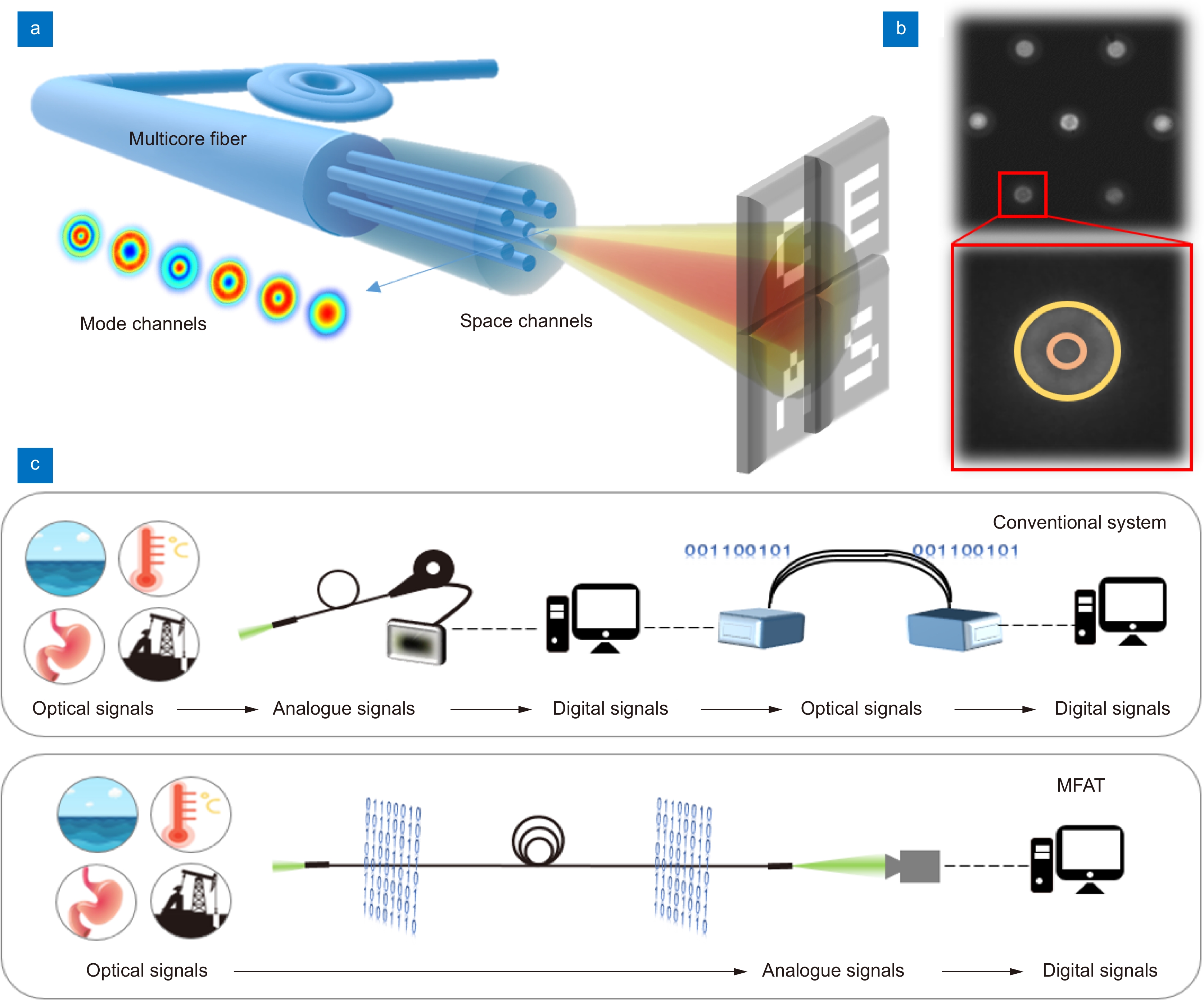
![Figure 1. Concept diagram of Multicore Fiber Acquisition and Transmission Image System (MFAT). (a) Different modes in different channels of a multicore fiber are excited by different incident angles of light (in red and yellow). (b) Directly acquired image of the proximal end face of a multicore fiber. The red region of interest zooms in on the detail of a fiber core. The yellow and orange circles divide two different areas for decoding. (c) Workflow of traditional optical fiber-based image acquisition and transmission and MFAT.]()
Concept diagram of Multicore Fiber Acquisition and Transmission Image System (MFAT). (a) Different modes in different channels of a multicore fiber are excited by different incident angles of light (in red and yellow). (b) Directly acquired image of the proximal end face of a multicore fiber. The red region of interest zooms in on the detail of a fiber core. The yellow and orange circles divide two different areas for decoding. (c) Workflow of traditional optical fiber-based image acquisition and transmission and MFAT.
All-optical acquisition and transmission enable images to be transmitted at the speed of light from one end to the other without additional electronic circuits. Fiber bundles have been proven to be able to directly transform and transmit two-dimensional optical fields end-to-end21−23, which makes them valuable in inaccessible and invisible areas, including extreme environments such as aerospace, industrial production, and medical endoscopy. However, they are typically short in length and expensive due to the manufacturing process, making it difficult to achieve guaranteed high quality over long distances. In recent years, many all-optical networks24−29 have been designed and learned to implement lens-free acquisition27, privacy propagation28, and image classification29, which are promising as the basis for next-generation communications. The combination with single-mode fiber bundles30 achieves long-range, interference-resistant, and low-latency propagation, but it is still difficult to fabricate the diffraction layer and usually only works with a laser.
Here, we propose an all-fiber multiplexed parallel acquisition and transmission one-piece system called Multicore Fiber Acquisition and Transmission Image System (MFAT). The electronic circuit-free front-end design eliminates the complex signal conversion process and it is suitable for most environments and robust to noise based on incoherent light. The image content is encoded in the optical domain through fiber coupling. The multichannel characteristics of multicore optical fibers are developed to achieve high capacity and quality transmission of encoded information (in Fig. 1(a)). Digital aperture filtering techniques have been shown to enable recovery and reconstruction from end-plane images that completely hide the original information, which makes it possible to achieve real-time scene reconstruction from 1 km away. We demonstrate the performance of the system in two modes, namely direct image transmission and coded transmission, and discuss the potential value of multidimensional optical field information. The scheme has great application in image acquisition and transmission over long distances and in extreme environments.
Method
Principle and implementation of MFAT
Compared with the conventional fiber-based image acquisition and transmission system, the proposed all-optical MFAT eliminates multiple signal conversion processes as shown in Fig. 1(c). The multiplexing of spatial and modal channels of the multicore fiber (MCF) ensures high-capacity parallel acquisition and transmission. The incident light field is optically encoded into different modes in different channels of the MCF. The low-interference, low-loss transmission of the optical fiber allows the encoded information to be transmitted over several kilometers. Based on the non-coherent optical properties, the modes at the fiber output are considered as a superposition of different spatial object points. By digital aperture decoding, the reconstruction of the light field at the distal can be achieved rapidly.
The optical encoding process is based on the excitation principle of fiber propagation modes31. Different angles of the same object point arriving at different core end faces excite different transmission modes as depicted in Fig. 2(a). For most natural scenarios, all mode components within a single channel can be viewed as a superposition of different modes of light excitation at all different object points. The incident light field is therefore encoded in the spatial and mode components of the multicore fiber. Few-mode fibers are used for long-distance transmission32. All mode components are output and recorded at the near end after long-distance transmission. Accurately obtaining the power of each mode is often difficult33,34, because the pixel-by-pixel computation of all the pixels corresponding to the cores requires large computational resources and limits the reconstruction time. Thus, a low-cost digital aperture decoding technique based on image processing techniques has been designed to quickly implement the reconstruction as shown in Fig. 2(b). Two feature values are computed by core masking and averaging for the yellow and orange regions to represent the features within each core, whose acquisition steps are detailed in the digital aperture decoding section of the method. The feature values of all the cores are sequentially arranged into a feature values matrix Y. The real image X can be fully recovered at the proximal end by solving Eq. (1). Therefore, the image transmission process can be viewed as a projection of spatial information on the dimension of the fiber optic transmission modes, while the feature values contain information about the superposition of all excitation modes recorded on the image sensor. The calibration matrix C is the response of different feature values to different spatial locations during transmission via MFAT, which can be obtained by calculation or calibration (see Calibration in Method for details). b is used to describe the system noise.
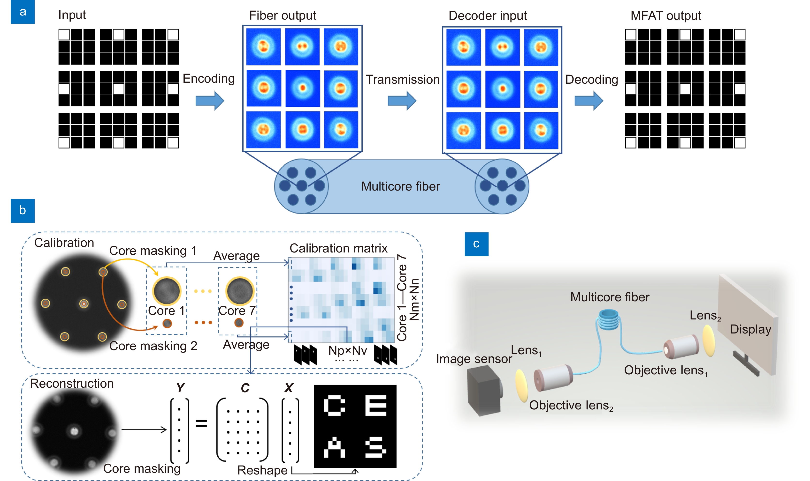
![Figure 2. Principle and implementation of MFAT. (a) The whole process of MFAT: image acquisition, encoding, multi-channel parallel transmission, and decoding. (b) Calibration and solving process based on digital aperture decoder. The yellow and orange circles indicate example averaging regions for full-aperture and center-aperture images, respectively. (c) Optical setup in experiments. The real image on the screen is displayed on the distal of the multicore fiber by a scaled combination of lens1 (f1 = 12 mm) and objective lens1 (50×). The pattern at the proximal of the multicore fiber is projected on the image sensor by a lens2 (f2 = 30 mm) and an objective lens2 (40×).]()
Principle and implementation of MFAT. (a) The whole process of MFAT: image acquisition, encoding, multi-channel parallel transmission, and decoding. (b) Calibration and solving process based on digital aperture decoder. The yellow and orange circles indicate example averaging regions for full-aperture and center-aperture images, respectively. (c) Optical setup in experiments. The real image on the screen is displayed on the distal of the multicore fiber by a scaled combination of lens1 (f1 = 12 mm) and objective lens1 (50×). The pattern at the proximal of the multicore fiber is projected on the image sensor by a lens2 (f2 = 30 mm) and an objective lens2 (40×).
{\boldsymbol{Y}} = {\boldsymbol{CX}} + {\boldsymbol{b}}\;. MFAT breaks through the limitation of the existing number of spatial channels and explores the multiplexing of spatial channels and intra-single core mode channels to establish a stable image acquisition-encoding-multi-channel parallel transmission-decoding process without any optoelectronic and analog-to-digital conversion. All-optical coding makes the device more compact while also compensating for the shortcomings of missing part of the spatial information due to insufficient sampling caused by large fiber core spacing. An enclosed, stable, and secure transmission system is more conducive to overcoming environmental interference and achieving direct observation of hard-to-reach areas. This work demonstrates two transmission modes, direct image transmission and encoded transmission, proving its expanded transmission capacity and satisfactory reconstruction quality.
Fiber-coupled encoder
Fiber-coupled self-encoders are based on the principle of fiber-coupled mode excitation31. The excitation and the coupling efficiency of the transmitted modes in the fiber are related to the spatial angle and position of the incident light from different object points in the scene. Even if two object points excite the same mode share within the same core, they can be distinguished based on other cores. Commercially available seven-core fibers can support about 6–10 modes in a single channel for visible light. They can both be obtained by calibration. The ratio {\alpha _{\rm{l}}} of the power of each mode can be described as Eq. (2). {P_{\rm{l}}} is the power of one kind of linear polarized mode and {P_{\rm{i}}} is the total incident power. k is the propagation coefficient. {r_0} is the modal spot size and {\rho _{\rm{s}}} is the beam spot size. {n_{\rm{i}}} represents the refractive index and {\theta _{\rm{i}}} represents the angle between the incident light and the fiber axis.
\begin{split} {\alpha _{\rm{l}}} =& \frac{{{P_{\rm{l}}}}}{{{P_{\rm{i}}}}} = 4\frac{{{{(k{\rho _{\rm{s}}}{n_{\rm{i}}}{\theta _{\rm{i}}})}^{2l}}}}{{l!}}{\left\{ {\left. {\frac{{{r_0}{\rho _{\rm{s}}}}}{{r_0^2 + \rho _{\rm{s}}^2}}} \right\}} \right.^{2l + 2}}\\ &\cdot {\rm{exp}} \left\{ {\left. { - \frac{{{{(k{\rho _{\rm{s}}}{n_{\rm{i}}}{\theta _{\rm{i}}}{r_0})}^2}}}{{r_0^2 + \rho _{\rm{s}}^2}}} \right\}} \right. \end{split}\;. The intensity distribution {S_l} for each transmission mode can be calculated from the fiber geometry and material parameters. When incoherent light is transmitted, the total intensity distribution S recorded at the output can be considered as a superposition of the intensities of the different transmission modes.
S = \sum\limits_l {{\alpha _l} \times {S_l}} \;. Digital aperture decoder
Accurately achieving mode separation and obtaining the power share of each mode is difficult. The digital aperture technique achieves the division of the fiber end face region and fast reconstruction by extracting the eigenvalues of different regions, consisting of three steps as shown in Fig. 2(b). Step 1: Obtain full and center aperture masks. A uniform white image is projected to the far end and transmitted through MFAT when calibrating. After testing different values of full aperture radius R1 and center aperture radius R2, the full aperture region is defined as the whole fiber core and the center aperture radius R2 is set to 1/3 R1. Step 2: Extraction of feature values for the end-face intensity distribution based on the full aperture mask and the center aperture mask, denoted as T1, and T2. The yellow and orange circles indicate example averaging regions for full-aperture and center-aperture images, respectively in Fig. 2(b). The feature values of seven cores are sequentially arranged as matrix Y. Step 3: Computational reconstruction. The real image can be solved by Eq. (1). When solving, the minimum L1-norm solution of the linear equation is obtained under certain constraints, such as scatter constraints at calibration, integer constraints, etc. by MATLAB.
Calibration
The calibration matrix C can be obtained directly by theoretical calculations when all the parameters of the components in the MFAT are precisely known. Typically, m×n pictures with pixel-by-pixel illumination are required before transmission of an image with m×n pixels. During the calibration process, the point source images of the corresponding resolution sizes are displayed on the monitor. The end-surface images calibrated at different spatial locations are recorded with the image sensor and their feature values are extracted based on a digital aperture decoder. After traversing the whole area, all the feature values are extracted to construct the calibration matrix C. Each column of C consists of 14 feature values at different locations in the object space, representing the response of MFAT for each pixel location. Each row of C represents the contribution of a different pixel location to a feature value.
Experimental setup
The experimental setup is shown in Fig. 2(c). The ground truth (GT) image is generated by displaying an 80×80-pixel sub area on a monitor (2560×1440, AOC, pixel spacing 206 μm). The scaling system consisting of lens1 (f1 = 30 mm, Thorlabs) and objective lens1 (50×, LMPlanFi, Olympus) reduces the GT by about 100 times and projects it to a position about 400 μm from the distal end face of the multicore fiber. The multicore fiber (MCF 7-42/150/250(SM), YOFC) has a cladding diameter of 150 μm and contains 7 cores. The core diameter is about 8.0 μm, and the spacing is about 41.5 μm. In the simple image transmission reconstruction process, a 1010-meter seven-core fiber was used (Fig. 3(b)). A 10.6-meter seven-core fiber was used in the natural image multidimensional reconstruction and encoded transmission reconstruction process. The image of the near-end face is recorded by lens2 (f2 = 12 mm, Thorlabs) and objective lens2 (40×, Daheng) at about 33.3 times to the image sensor (panda 4.2, PCO).
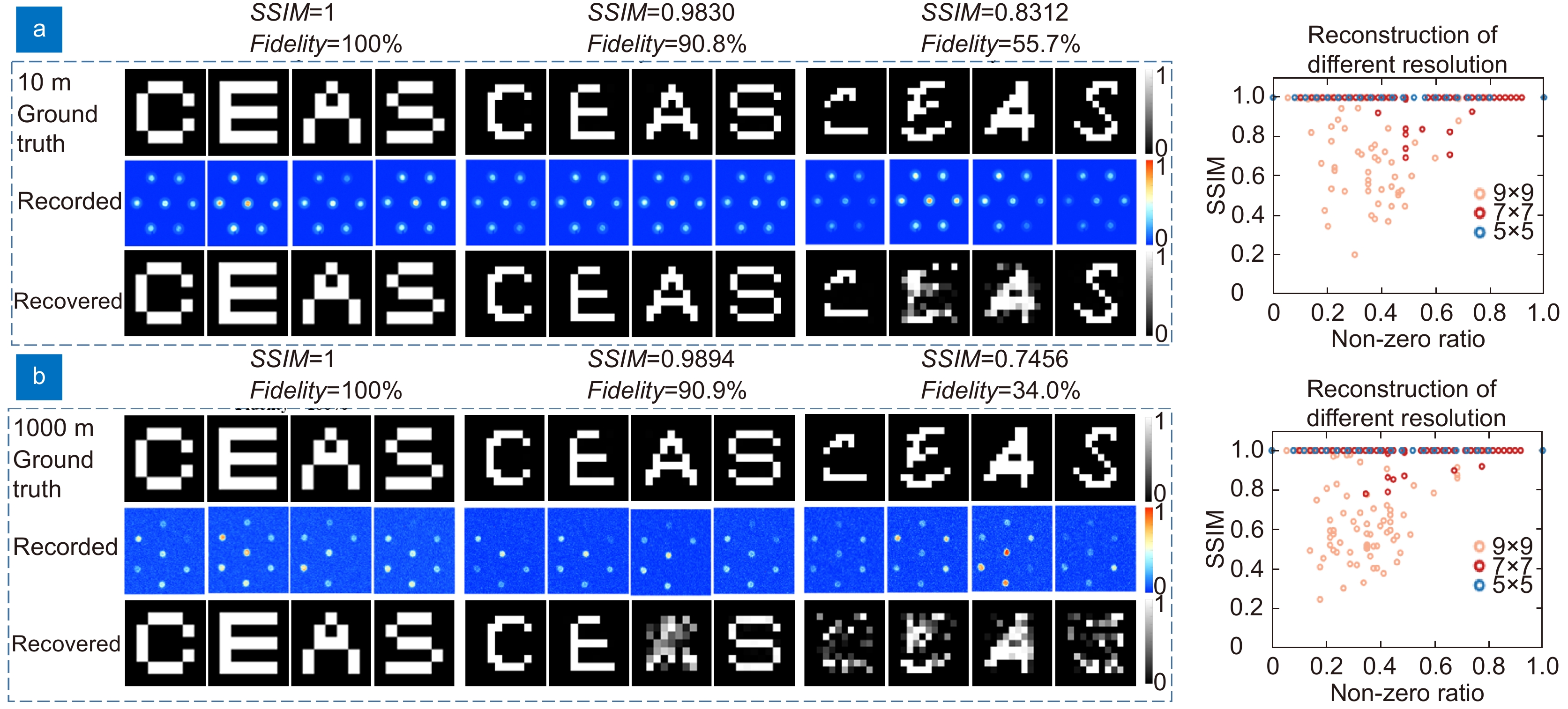
![Figure 3. Direct transmission performance of simple images. (a) Left: Patterns at the output of a multicore fiber after a transmission distance of 10 m for images of different resolutions and the reconstruction results after digital aperture decoding. The Structure Similarity Index Measure (SSIM) and fidelity decrease with increasing image resolution. Right: SSIM reconstruction results for all test images. (b) Left: Transmission and reconstruction results at an ultra-long distance (1010 m). Right: SSIM reconstruction results for all test images. Sparse images can be fully reconstructed. The intensity of the record is normalized.]()
Direct transmission performance of simple images. (a) Left: Patterns at the output of a multicore fiber after a transmission distance of 10 m for images of different resolutions and the reconstruction results after digital aperture decoding. The Structure Similarity Index Measure (SSIM) and fidelity decrease with increasing image resolution. Right: SSIM reconstruction results for all test images. (b) Left: Transmission and reconstruction results at an ultra-long distance (1010 m). Right: SSIM reconstruction results for all test images. Sparse images can be fully reconstructed. The intensity of the record is normalized.
Results
Simple images direct transmission
Simple images at a distance are transmitted directly by MFAT based on the optical setup in Fig. 2(c). Commercial seven-core fiber is used to test the transmission of image information far beyond its spatial channel count. To facilitate the evaluation of MFAT performance, binarized data sets (consisting of 26 letters, 10 numbers from 0 to 9, and a number of random scatter plots with different sparsity) are constructed at different resolutions. Fig. 3(a) shows the transmission reconstruction effect of MFAT for different (5×5, 7×7, and 9×9) resolution images at a transmission distance of 10 meters. The real pixel sizes of the three types of images are 33.1 μm, 23.6 μm, and 18.4 μm. For the 25-pixel image, the MFAT reconstructed image achieves a 100% structural similarity coefficient and 100% fidelity with the real image (the first row). In general, the Structure Similarity Index Measure (SSIM) of image reconstruction decreases as the number of image pixels increases, which is limited by the transmission capacity and determined by the solution method of Eq. (1). However, for the 49-pixel image and the 81-pixel image, our decoding method allows to still keep it at 0.98 and 0.83. Good fidelity is obtained for sparse images while some complex images have reconstruction errors because the obtained solutions are not unique. The impact of different transmission losses within the fiber core on the system increases as the transmission distance increases, resulting in a reduced signal-to-noise ratio and affecting the quality of the feature values extracted at the near end. This effect is more pronounced after 1010 m transmission and reconstruction as shown in Fig. 3(b). MFAT can maintain the reconstruction quality of SSIM = 1, 0.9812, and 0.80 for images of different resolutions (5×5, 7×7, and 9×9) but the fidelity drops from 100% to 34.9%. The right subplot shows the reconstructed SSIM for each image. The horizontal coordinates Non-zero ratio is used to indicate different sparsity levels. Sparse images are more likely to be fully reconstructed when the image resolution is increased because there is a tradeoff between the reconstruction resolution and the system robustness. In order to obtain some robustness to meet the requirements of non-coherent optical transmission scenarios, we provide a low-cost and fast feature extraction and digital decoding method. A part of channel information is sacrificed to resist noise. Images larger than the channel capacity but sparser can still achieve good recovery under noise. More methods applicable to pattern feature extraction within incoherent optical cores are also applicable to our system.
Although direct transmission of images is common in optical fiber bundles-based endoscopes, conventional fiber- endoscopy techniques are difficult to achieve online viewing over ultra-long distances (more than 1 km). Our encoding and decoding schemes can also be transferred to existing schemes to increase the channel capacity to enhance image quality or improve spatial resolution. Theoretically, the reconstruction quality of patterns is limited by the channel capacity of the system. The tens of times higher number of channels compared to single-mode fiber makes direct image transmission possible. Additionally, the multiplexing of channels such as wavelength and polarization is also applicable to enhance the system transmission capacity, the same as shown in optical fiber communication. More details on the quality of the reconstruction can be found in the analysis of the resolution in Discussion.
Multi-dimensional images direct transmission
In addition to the transmission of binary simple graphics, natural grayscale images have also been shown to be able to be reconstructed by MFAT. As shown in Fig. 4(a), 5×5-pixel images containing multiple gray levels were tested. A polarizer was added in front of the camera at the acquisition end to obtain more channel capacity. By acquiring the calibration image and the test image in two orthogonal polarization states (the second and third rows in Fig. 4(a)), the reconstructed image identical to the real image (first row) is shown in the fourth row of Fig. 4(a). The experimental results show that MFAT has almost zero error for the reconstruction under this condition. Similarly, some errors arise with increasing image spatial resolution and gray level, which are also affected by the system channel capacity and signal-to-noise ratio. The results of insufficient system channel capacity are presented in the discussion.
![Figure 4. Results of multidimensional image transfer and reconstruction. (a) Natural grayscale images are transferred and reconstructed by MFAT as a result. Two polarization (P1 and P2) end-maps are recorded and the intensity is normalized. 5×5-pixel grayscale maps can be completely reconstructed by 100%. (b) The results of the acquisition and reconstruction of RGB trichromatic images. Two polarization (P1 and P2) end-maps are recorded for decoding. 5×5-pixel color maps can be accurately reconstructed.]()
Results of multidimensional image transfer and reconstruction. (a) Natural grayscale images are transferred and reconstructed by MFAT as a result. Two polarization (P1 and P2) end-maps are recorded and the intensity is normalized. 5×5-pixel grayscale maps can be completely reconstructed by 100%. (b) The results of the acquisition and reconstruction of RGB trichromatic images. Two polarization (P1 and P2) end-maps are recorded for decoding. 5×5-pixel color maps can be accurately reconstructed.
Color images tend to contain much richer information for a better visual experience. Different wavelengths of incident light can often excite different modes with different power occupancy ratios. Each wavelength also has a different transmission loss in the fiber, which introduces different levels of noise into the system after a certain distance of transmission. Besides, a lens set is usually present at the far end to achieve large depth-of-field imaging. The chromatic aberration causes a certain spatial lateral misalignment at the same location in the scene when illuminated on the fiber end face, which is encoded and transmitted by the optical encoding and recorded by collecting the in-core pattern. The extraction of spectrally correlated different in-core patterns allows us to easily reconstruct multispectral images. By calibrating the response of the system to different wavelengths at the same pixel position, patterns composed of multiple colors are reconstructed based on two orthogonal polarization states to increase the system transmission capacity. Different wavelengths occupy different transmission channels. For the same size image, a color image of RGB usually requires three times the transmission capacity of a grayscale image. Different single-spectrum images and mixed images of different spectra are used for testing as shown in Fig. 4(b). The images at the output of the fiber under both polarization channels were recorded separately to ensure fully accurate recovery of the original image. As shown in the last row, the 5×5 trichromatic image reconstruction has 100% fidelity.
High-quality encoded transmission
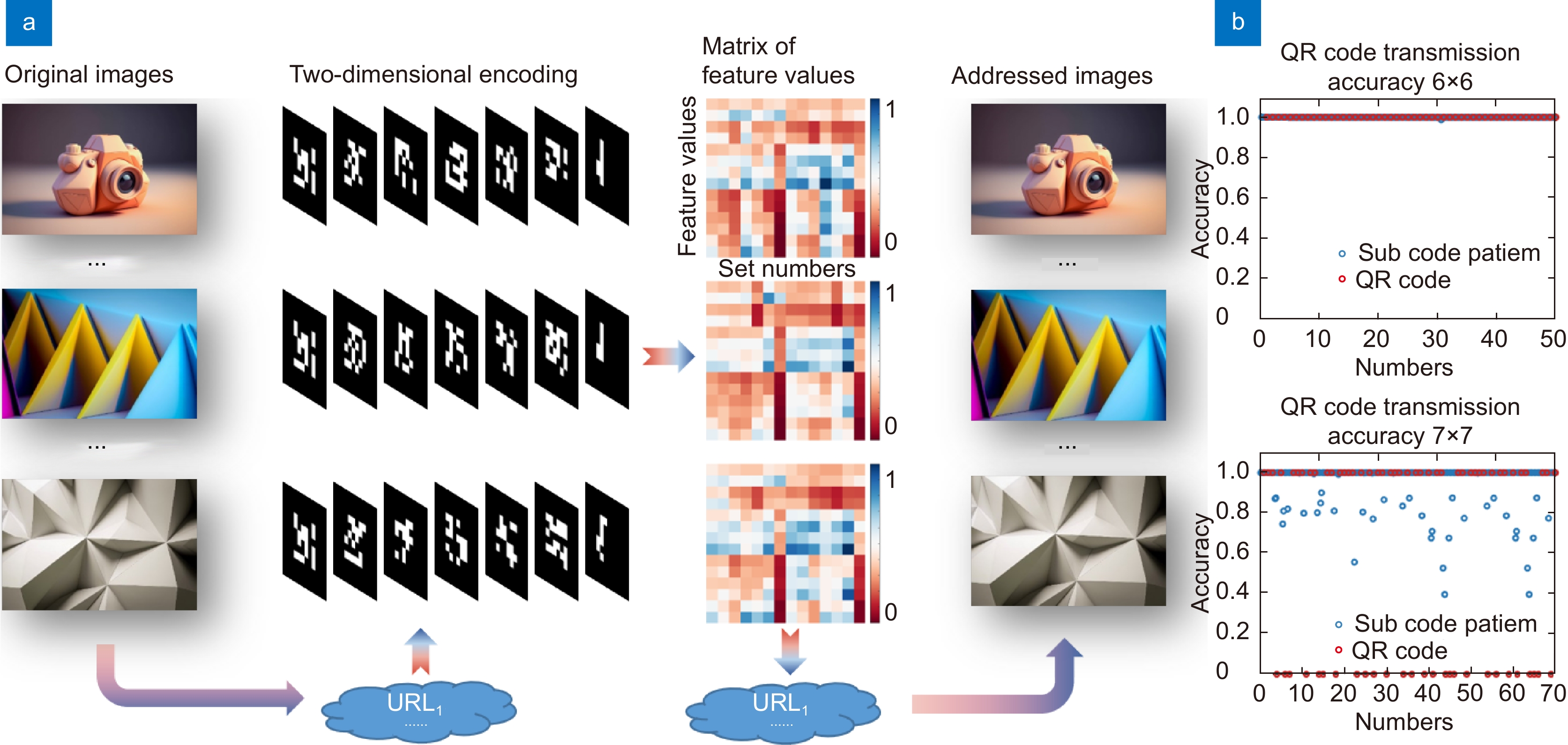
In spite of the direct all-fiber acquisition, encoding, and transmission of the optical field, MFAT is also applicable to long-distance encoded transmission of multimodal, high-quality data, including text, audio, and high-definition images. Typically, images are compressed encoded, and converted into a time-series digital signal to be transmitted through a modulator. Compared to traditional single-mode fiber-based optical networks, MFAT has more parallel channels, allowing for a larger capacity per unit of time. As shown in Fig. 5, the access address of the high-quality image (1280×960) stored in the cloud is encoded and transmitted by seven 6×6-pixel simple binary images. 14 feature values are extracted from each transmitted binary image by a digital aperture decoder. The feature value matrix is constructed by obtaining 14 sets of feature value information based on two polarization states and 6 coded images. By solving this matrix, the original information can be reproduced. 50 high-quality images are transmitted and 100% completely reconstructed. In addition, five 7×7-pixel binary images were tested for encoding the information as well. As the size of the 2D coded image increases with a single transmission, a certain degree of error occurs as shown in Fig. 5(b). To ensure high-quality reconstruction of larger data without exceeding the transmission capacity, it is necessary to choose the appropriate size of coded maps for different multicore fibers.
![Figure 5. Results of high-quality encoded transmission. (a) Flow chart of high-quality MFAT-based encoded acquisition and transmission. The cloud storage address of high-definition images is encoded into seven 6×6-pixel 2D maps for transmission via MCF. Fast access is possible based on the reconstructed address. (b) Quality of transmission reconstruction with different encoding sizes.]()
Results of high-quality encoded transmission. (a) Flow chart of high-quality MFAT-based encoded acquisition and transmission. The cloud storage address of high-definition images is encoded into seven 6×6-pixel 2D maps for transmission via MCF. Fast access is possible based on the reconstructed address. (b) Quality of transmission reconstruction with different encoding sizes.
The high-definition images are usually stored in the cloud and can be accessed through their uniform resource locators (URLs). The image URLs were encoded based on the base64 encoding principle to get their corresponding QR (Quick Response) code, which is nearly 100% accurate when the transmission capacity is small. Only parts of the QR code were intercepted sequentially by column and rearranged into 6×6 or a specific required size according to certain encoding rules for transmission. The encoding can be set by the user. The real URL information can be obtained by MFAT transmission reconstruction and based on the encryption method. Access to high-definition images can be achieved over long distances. The combination of optical coding and digital coding35,36 can be achieved by combining the two-dimensional coding algorithm with the hardware optical circuit. This two-dimensional encoding mode of transmission greatly achieves the confidentiality of the transmitted data, and the degree of confidentiality is determined by the encoding method. Even if the data is truncated during transmission, it is difficult to recover without encoding rules and optical path encoding at the transmitter.
Discussion
With optical domain data stream processing including fiber-coupled encoding, multi-channel parallel transmission and digital aperture decoding, MFAT increases transmission capacity by an order of magnitude and saves signal conversion time by eliminating the need for additional electronic components compared to existing conventional methods. It has more than 100 times the transmission distance compared to fiber-based image direct transmission methods. The ultra-long-range direct image transmission makes it a great potential for applications in hard-to-reach areas such as instrumentation monitoring, damage detection, clock synchronization, etc. in the deep sea, oil wells, and aerospace.
2D information reconstruction quality is influenced by transmission capacity, system signal-to-noise ratio, and reconstruction algorithm in MFAT. With a guaranteed fidelity of 0.85, MFAT transmits a binary image of 81 pixels through 7 channels, an order of magnitude increases in capacity compared to conventional single-mode fiber transmission systems. Typically, the transmission capacity of a fiber optic system can be described by Eq. (4)37,38:
TC = M \times B \times {N_{\rm{b}}} \times (1 + R) \;. M denotes the total number of channels of the system. B denotes the system bandwidth and Nb is used to represent the modulation order of the code. R is the quality factor of the system and is related to the signal-to-noise ratio of the system. The theoretical system transmission capacity is related to the number of all cores (Ms) and the total number of modes (Mm) supported for transmission, which determines the resolution and bit depth of the transmitted images. Additional channels are required for grayscale levels and color dimensions. In addition, multidimensional information such as wavelength (Mλ) and polarization (Mp) contribute to a significant increase in system transmission capacity.
M = {M_\lambda } \times {M_{\rm{p}}} \times {M_{\rm{m}}} \times {M_{\rm{s}}} \;. As shown in the second and third rows of Fig. 6(a), the number of channels is insufficient (M ≈ 70) when only one wavelength or polarization channel is used to transmit the high-resolution image. The reconstructed 81-pixel image deviates from the real image. Two polarization directions or different wavelength channels were developed to improve the number of transmission channels (M ≈ 140) of the system and a completely accurate reconstruction (Fig. 6(a), the last row) is achieved, meaning that it can be combined with other existing multiplexing methods to further improve transmission throughput. The system is affected by the coupling coding efficiency \alpha , the transmission loss \beta , the noise {P_{{\mathrm{back}}}} of the image acquisition device, and mode crosstalk loss {P_{\mathrm{m}}} . The noise level \eta is used here to describe the system noise, as shown in Eq. (6).
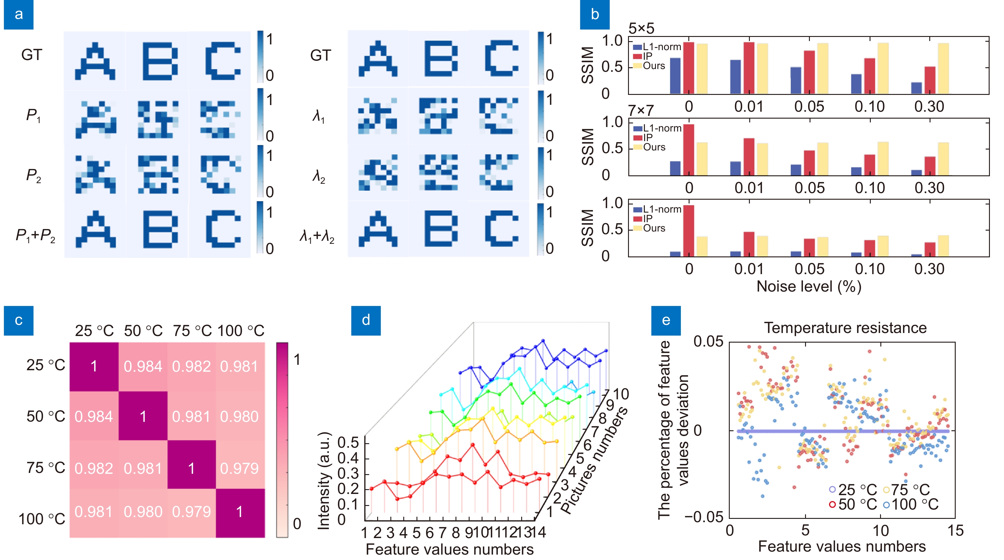
![Figure 6. (a) Some bias exists in the reconstruction of a single polarization or wavelength channel when the complexity of the transmitted image is greater than the transmission capacity. P1 and P2 represent two different polarization directions. λ1 and λ2 are red and green channels. More channels are developed to constrain finding the optimal solution. (b) Simulation results of reconstruction with different algorithms at different noise levels. (c) Correlation coefficients of images acquired at different temperatures. (d) The feature values correspond to different images at 25 °C. (e) Deviation of the feature values from the standard feature values at different temperatures.]()
(a) Some bias exists in the reconstruction of a single polarization or wavelength channel when the complexity of the transmitted image is greater than the transmission capacity. P1 and P2 represent two different polarization directions. λ1 and λ2 are red and green channels. More channels are developed to constrain finding the optimal solution. (b) Simulation results of reconstruction with different algorithms at different noise levels. (c) Correlation coefficients of images acquired at different temperatures. (d) The feature values correspond to different images at 25 °C. (e) Deviation of the feature values from the standard feature values at different temperatures.
\eta = \frac{{{P_{\rm{S}}} \times \alpha \times \beta \times {{z}} + {P_{{\rm{back}}}}{\mathrm{ + }}{P_{\mathrm{m}}}}}{{{P_{\rm{S}}} \times \alpha }} \;. {P_{\mathrm{S}}} expresses the raw 2D information power and z is the transmission distance. \beta is usually related to the intrinsic absorption of the fiber material and bending loss, typically in the range of 6–20 dB/km when observing visible light (400–780 nm) scenes. Noise affects the accuracy of the acquired data Y and the solution of Eq. (1). Some channel numbers are sacrificed to increase the robustness of the system. The reconstruction effects of different algorithms with different noise levels are simulated as shown in Fig. 6(b). For images of 5×5-pixels size, the proposed method can achieve 100% accurate reconstruction against noise levels of 5%. Our scheme outperforms the common L1 least squares solution and linear programming (LP) solution when the noise level is high. When the number of image pixels is larger than the number of extracted feature values, the decoding process is viewed as the solution to an underdetermined problem. Sparse images are more likely to be reconstructed accurately. Developing more channels helps to find multidimensional image information. The use of some randomly distributed scatter plots in the calibration process helps to constrain the problem.
Besides, the all-fiber one-piece acquisition and transmission architecture breaks through the limitations of most commercial semiconductor components used in environments from 0 °C to 70 °C. MFAT can theoretically withstand temperatures close to 800 °C almost. A certain length of fiber is heated on a hot bench to test the noise from different ambient temperatures (25 °C, 50 °C, 75 °C and 100 °C). The end-face maps of the multicore fibers at different temperatures containing the feature value information are recorded and the correlation coefficients between them are calculated as shown in Fig. 6(c). The correlation coefficients were kept above 0.98 (due to camera bottom noise). The feature values corresponding to different images at 25 °C are considered to be standard as illustrated in Fig. 6(d). Their {P_{\mathrm{m}}} deviations due to temperature are less than 5%, which is acceptable for MFAT (Fig. 6(e)). In addition, the transmission and reconstruction performance of MFAT under different bending states is demonstrated in the Supplementary information. The robustness of bending makes it highly promising for long-distance parallel transmission of images. The reconstruction speed of the image depends on the sampling rate of the detector and the speed of the reconstruction algorithm. An 81-pixel binary map takes 0.03 s to reconstruct with a 2.9-GHz Intel Core i5-9400F central processing unit (CPU) (8 GB RAM). Other solution methods including algorithms based on all-optical computing and deep learning are also considered to achieve rapid reconstruction of arbitrary images. The transmission rate of the system is theoretically limited by the speed of light. High-speed photodetectors39 integrated at the fiber end face adapted to digital aperture technology will replace the image sensors and greatly increase the effective transmission rate of the system in the future.
Conclusions
In conclusion, we propose an electronic component-free method for image acquisition and long-distance transmission. It integrates optical coding, encryption, compression, transmission, and decoding processes into the fiber saving the steps and time for data mode conversion. Two transmission modes are demonstrated: the ultra-long image direct transmission breaks through the transmission distance of the original image transmission fiber. The two-dimensional encoding transmission mode is suitable for the encrypted transmission of multiple data formats. The simultaneous multiplexing of time and spatial channels increases its transmission capacity by several orders of magnitude. The interference-resistant, compact structure lays the foundation for globalized high-speed real-time media streaming. The development and utilization of more dimensional information and the combination with more high-performance algorithms also offer the possibility of next-generation all-optical parallel transmission systems.
Acknowledgements
We are grateful for financial supports from the National Key R&D Program of China (2021YFA1401103) and the National Natural Science Foundation of China (61925502 and 51772145).
-
References
[1] Yang JC, Wang CG, Jiang B et al. Visual perception enabled industry intelligence: state of the art, challenges and prospects. IEEE Trans Ind Inform 17, 2204–2219 (2021).
DOI: 10.1109/TII.2020.2998818[2] Esteva A, Chou K, Yeung S et al. Deep learning-enabled medical computer vision. npj Digit Med 4, 5 (2021).
DOI: 10.1038/s41746-020-00376-2[3] Guan BO, Jin L, Ma J et al. Flexible fiber-laser ultrasound sensor for multiscale photoacoustic imaging. Opto-Electron Adv 4, 200081 (2021).
DOI: 10.29026/oea.2021.200081[4] Ma XD, Fan MZ, Cai YQ et al. A Fabry–Pérot fiber-optic array for photoacoustic imaging. IEEE Trans Instrum Meas 71, 4501508 (2022).
[5] Yang LY, Li YP, Fang F et al. Highly sensitive and miniature microfiber-based ultrasound sensor for photoacoustic tomography. Opto-Electron Adv 5, 200076 (2022).
DOI: 10.29026/oea.2022.200076[6] Zhao HX, Li K, Yang F et al. Customized anterior segment photoacoustic imaging for ophthalmic burn evaluation in vivo. Opto-Electron Adv 4, 200017 (2021)
View full references list -
Cited by
Periodical cited type(4)
1. Macedo, L., Frizera, A., Nedoma, J. et al. Rayleigh scattering-based distributed sensing in multicore optical fibers for shape reconstruction in multiplanar disturbance. Measurement Journal of the International Measurement Confederation, 2025. DOI:10.1016/j.measurement.2025.118101 2. Zhao, L., Yang, H., Sun, T. et al. Model Design and Study of a U-Channel Photonic Crystal Fib Optic Sensor for Measuring Glucose Concentration in Blood. Sensors, 2025, 25(9): 2647. DOI:10.3390/s25092647 3. Zhao, X., Qi, H., Zhang, Y. et al. Effects of H2O and SF6 on CO Molecular Relaxation in a Cantilever-Enhanced Fiber-Optic Photoacoustic Sensor. Analytical Chemistry, 2025, 97(14): 7938-7944. DOI:10.1021/acs.analchem.5c00062 4. Li, W., Long, Y., Yan, Y. et al. Wearable photonic smart wristband for cardiorespiratory function assessment and biometric identification. Opto Electronic Advances, 2025, 8(5): 240254. DOI:10.29026/OEA.2025.240254 Other cited types(0)
-
Author Information
-
Supplementary Information
TitleActions -
Copyright
Open Access. © The Author(s). This article is licensed under a Creative Commons Attribution 4.0 International License. To view a copy of this license, visit http://creativecommons.org/licenses/by/4.0/. -
About this Article
Cite this Article
Haogong Feng, Xi Chen, Runze Zhu, et al. Seeing at a distance with multicore fibers. Opto-Electronic Advances 7, 230202 (2024). DOI: 10.29026/oea.2024.230202Download CitationArticle History
- Received Date October 31, 2023
- Accepted Date February 28, 2024
- Available Online June 04, 2024
- Published Date July 15, 2024
Article Metrics
Article Views(3071) PDF Downloads(762)
 OE Journals Group

Focuses on the advances of the cutting edge innovations of optics, photonics and optoelectronics
JCR Impact Factor: 22.4
CiteScore: 26.8
Open Access