
 E-mail Alert
 RSS
RSS
| Citation: |
Dong Y C, Li X M, Chen X L, et al. Analysis of pointing error of Risley grating tracking system[J]. Opto-Electron Eng, 2025, 52(3): 240241. doi: 10.12086/oee.2025.240241

|
Analysis of pointing error of Risley grating tracking system
-
Abstract
The Risley grating tracking system is mainly composed of two rotating polarization gratings. The light source is diffracted by the polarization grating to achieve beam pointing in the conical range, and then the target is captured and tracked. As an important index of the Risley grating tracking system, pointing accuracy is not only affected by servo and optical systems but also by system errors such as antenna installation accuracy and shafting assembly error of double grating turntable in the Risley grating tracking system. Therefore, this paper mainly analyzes the systematic error sources in the Risley grating tracking system and the pointing errors caused by them. First, a mathematical model of systematic error is established and verified by ZEMAX. Then, MATLAB is used to analyze the influence of each systematic error source on the pointing error of the Risley grating tracking system. Finally, according to the analysis results and index requirements, the error source of a double grating tracking system is assigned to guide the design and installation of the double grating turntable. The actual maximum pointing error of the double grating turntable δe=7.2" is obtained after several experimental tests, which satisfies the design index of pointing error of the double grating turntable 10".-
Keywords:
- Risley grating /
- tracking system /
- pointing error /
- error distribution
-

-
References
[1] 姜会林, 佟首峰. 空间激光通信技术与系统[M]. 北京: 国防工业出版社, 2010. Jiang H L, Tong S F. The Technologies and Systems of Space Laser Communication[M]. Beijing: National Defense Industry Press, 2010. [2] 谢木军, 马佳光, 傅承毓, 等. 空间光通信中的精密跟踪瞄准技术[J]. 光电工程, 2000, 27(1): 13−16. doi: 10.3969/j.issn.1003-501X.2000.01.003 Xie M J, Ma J G, Fu C Y, et al. Precision tracking and pointing technologies in space optical communication[J]. Opto-Electron Eng, 2000, 27(1): 13−16. doi: 10.3969/j.issn.1003-501X.2000.01.003 [3] Schwarze C R, Vaillancourt R, Carlson D, et al. Risley-prism based compact laser beam steering for IRCM, laser communications, and laser radar[J]. Critical Technology, 2005, 9: 1−9. [4] Hakun C, Budinoff J, Brown G, et al. A boresight adjustment mechanism for use on laser altimeters[EB/OL]. [2023-03-01]. https://esmats.eu/amspapers/pastpapers/pdfs/2004/hakun.pdf. [5] 余辉龙, 鲍智康, 王璇, 等. XY-2号卫星激光通信载荷PAT在轨测试[J]. 红外与激光工程, 2021, 50(5): 20200327. doi: 10.3788/IRLA20200327 Yu H L, Bao Z K, Wang X, et al. XY-2 satellite laser communication equipment PAT test in orbit[J]. Infrared Laser Eng, 2021, 50(5): 20200327. doi: 10.3788/IRLA20200327 [6] 宋一诺. 基于旋转双棱镜的激光通信粗指向机构关键技术研究[D]. 长春: 中国科学院大学(中国科学院长春光学精密机械与物理研究所), 2023. https://doi.org/10.27522/d.cnki.gkcgs.2023.000004. Song Y N. Key technology research of coarse pointing mechanism for laser communication based on Risley prisms[D]. Changchun: Changchun Institute of Optics, Fine Mechanicsand Physics, Chinese Academy of Sciences, 2023. https://doi.org/10.27522/d.cnki.gkcgs.2023.000004. [7] Wang J, Gao L, Jiang L, et al. Establishment and verification of formulas of target tracking based on dual liquid crystal polarization gratings[J]. Opt Express, 2022, 30(24): 43062−43077. doi: 10.1364/OE.473947 [8] Oh C, Kim J, Muth J F, et al. A new beam steering concept: Risley gratings[J]. Proc SPIE, 2009, 7466: 74660J. doi: 10.1117/12.828005 [9] Kim J, Miskiewicz M N, Serati S, et al. Nonmechanical laser beam steering based on polymer polarization gratings: design optimization and demonstration[J]. J Lightw Technol, 2015, 33(10): 2068−2077. doi: 10.1109/JLT.2015.2392694 [10] Zhou Y, Fan D P, Fan S X, et al. Laser scanning by rotating polarization gratings[J]. Appl Opt, 2016, 55(19): 5149−5157. doi: 10.1364/AO.55.005149 [11] 李小明, 朱国帅, 郭名航, 等. 基于光学自准直的旋转轴平行度测量与不确定度分析[J]. 红外与激光工程, 2023, 52(5): 20220794. doi: 10.3788/IRLA20220794 Li X M, Zhu G S, Guo M H, et al. Coaxiality measurement and uncertainty analysis of rotating shafts based on autocollimation[J]. Infrared Laser Eng, 2023, 52(5): 20220794. doi: 10.3788/IRLA20220794 [12] 符红, 吴琼, 林斌, 等. 基于双光栅的平行度检测[J]. 光电工程, 2012, 39(7): 61−66. doi: 10.3969/j.issn.1003-501X.2012.07.010 Fu H, Wu Q, Lin B, et al. The measurement of parallelism based on diffraction grating[J]. Opto-Electron Eng, 2012, 39(7): 61−66. doi: 10.3969/j.issn.1003-501X.2012.07.010 [13] 佀明华, 王伟明, 张勇, 等. 基于光电伺服平台的动态角度测量方法研究[J]. 光电工程, 2019, 46(10): 180445. doi: 10.12086/oee.2019.180445 Si M H, Wang W M, Zhang Y, et al. Research on dynamic angle measurement method based on electro-optical servo platform[J]. Opto-Electron Eng, 2019, 46(10): 180445. doi: 10.12086/oee.2019.180445 [14] 奚玉鼎, 于涌, 丁媛媛, 等. 一种快速搜索空中低慢小目标的光电系统[J]. 光电工程, 2018, 45(4): 170654. doi: 10.12086/oee.2018.170654 Xi Y D, Yu Y, Ding Y Y, et al. An optoelectronic system for fast search of low slow small target in the air[J]. Opto-Electron Eng, 2018, 45(4): 170654. doi: 10.12086/oee.2018.170654 -
Overview
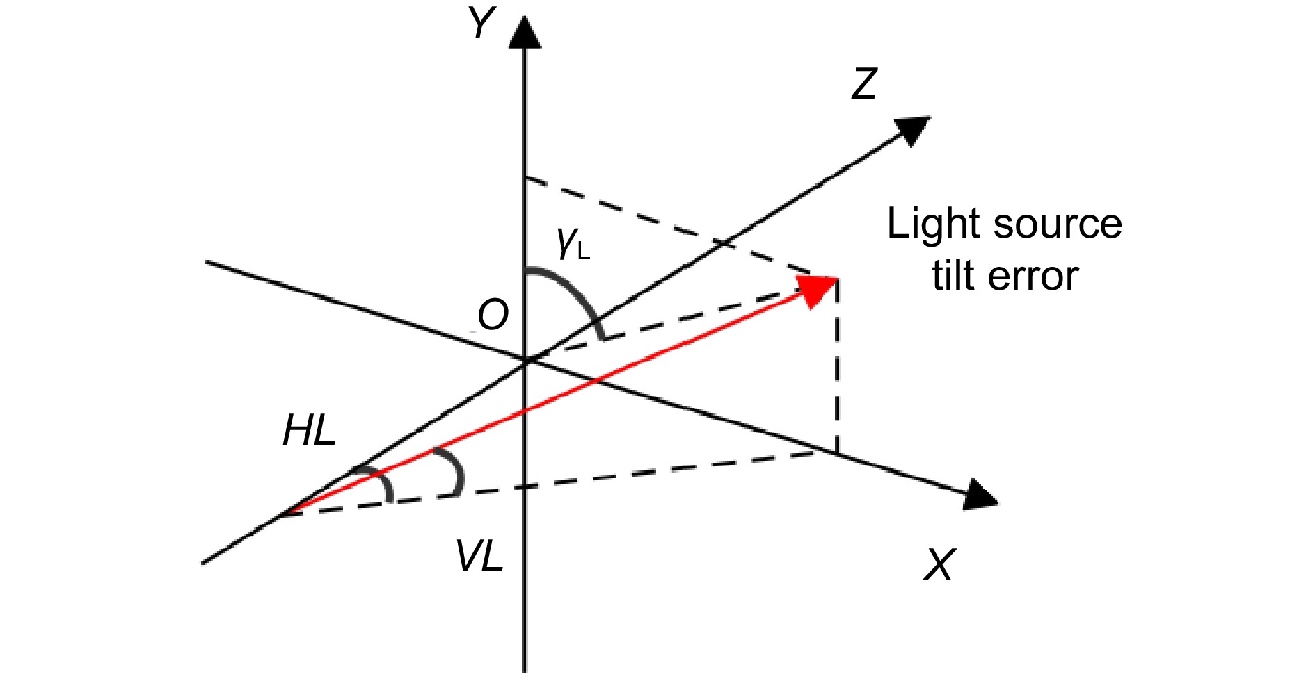
With the continuous progress of science and technology, laser application technologies such as space laser communication and photoelectric tracking continue to develop, and the requirements for tracking systems are becoming higher and higher. The Risley grating tracking system is small in size and light in weight, which can be used in some specific environments. The system is mainly composed of two rotating polarization gratings, through the diffraction of polarization gratings to achieve the direction of the beam in the conical range, so as to achieve the acquisition and tracking of the target. As an important index of the Risley grating tracking system, pointing accuracy is not only related to the servo system and optical system but also affected by system errors in the Risley grating turntable. Therefore, in this paper, systematic error sources in the Risley grating tracking system are classified and analyzed, and a systematic error source model is established, which mainly includes light source tilt error, grating axis tilt error, grating tilt error, and grating angle error.
The polar angle and azimuth angle of the outgoing beam under the error model are obtained by introducing the error angle, and verified by ZEMAX optical software. The results show that the maximum difference between the polar angle and the azimuth angle is 0.00076 "and 0.0013", respectively. After verification, MATLAB software was used to simulate the influence of each error source on the pointing error of the Risley grating tracking system. When each system error was set to 0.1°, the influence of light source tilt error and grating angle error on pointing error was 0.1035° and 0.01305°, respectively. The grating axis tilt error and the grating tilt error are both 3.168". Finally, according to the sensitivity of each error source to the pointing error, the four errors are assigned and corresponding to the Risley grating turntable, which guides the design, processing, and installation of the turntable. After the Risley grating turntable is finished, the pointing accuracy of the Risley grating turntable is verified by experiments. Multiple experimental results show that the actual maximum pointing error of the Risley grating turntable δe=7.2", which meets the design index of 10".
-
Access History

Figures(16)
Tables(5)
Article Metrics
Export File
Citation
Dong Y C, Li X M, Chen X L, et al. Analysis of pointing error of Risley grating tracking system[J]. Opto-Electron Eng, 2025, 52(3): 240241. doi: 10.12086/oee.2025.240241
Format
Content
 DownLoad:


-
Figure 1.
Schematic diagram of the Risley grating tracking system. (a) Structure principle; (b) Diffraction angle
-
Figure 2.
Main error sources of the system
-
Figure 3.
Risley grating tracking system error model
-
Figure 4.
ZEMAX error verification model and coordinate system diagram
-
Figure 5.
Simulation comparison between polar angle θ1 and azimuth angle φ1. (a) Polar angle θ1 comparison; (b) Azimuth angle φ1 comparison
-
Figure 6.
Simulation comparison between polar angle θ2′ and azimuth angle φ2′. (a) Polar angle θ2′ comparison; (b) Azimuth angle φ2′ comparison
-
Figure 7.
Simulation comparison between grating axis and grating tilt. (a) Comparison of polar angle θ3 ; (b) Comparison of azimuth angle φ3 ;(c) Maximum polar angle difference change; (d) Maximum azimuth angle difference change
-
Figure 8.
Tilt direction of the light source tilt error
-
Figure 9.
Pointing error caused by the light source tilt error. (a) Pointing error at HL=0.1°; (b) Pointing error at VL=0.1°; (c) Maximum pointing error varies with γL; (d) Maximum pointing error varies with the tilt error of the light source
-
Figure 10.
Pointing error caused by grating axis tilt error. (a) Pointing error at HR1=0.1°; (b) Pointing error at VR1=0.1°; (c) Pointing error at HR2=0.1°; (d) Pointing error at VR2=0.1°; (e) Maximum pointing error varies with γR1; (f) Maximum pointing error varies with γR2; (g) Change of the maximum pointing error with the tilt error of the grating axis
-
Figure 11.
Pointing error caused by grating angle error. (a) Pointing error at δψ1=0.1°; (b) Pointing error at δψ2=0.1°; (c) Change of the maximum pointing error with the angle error of the grating
-
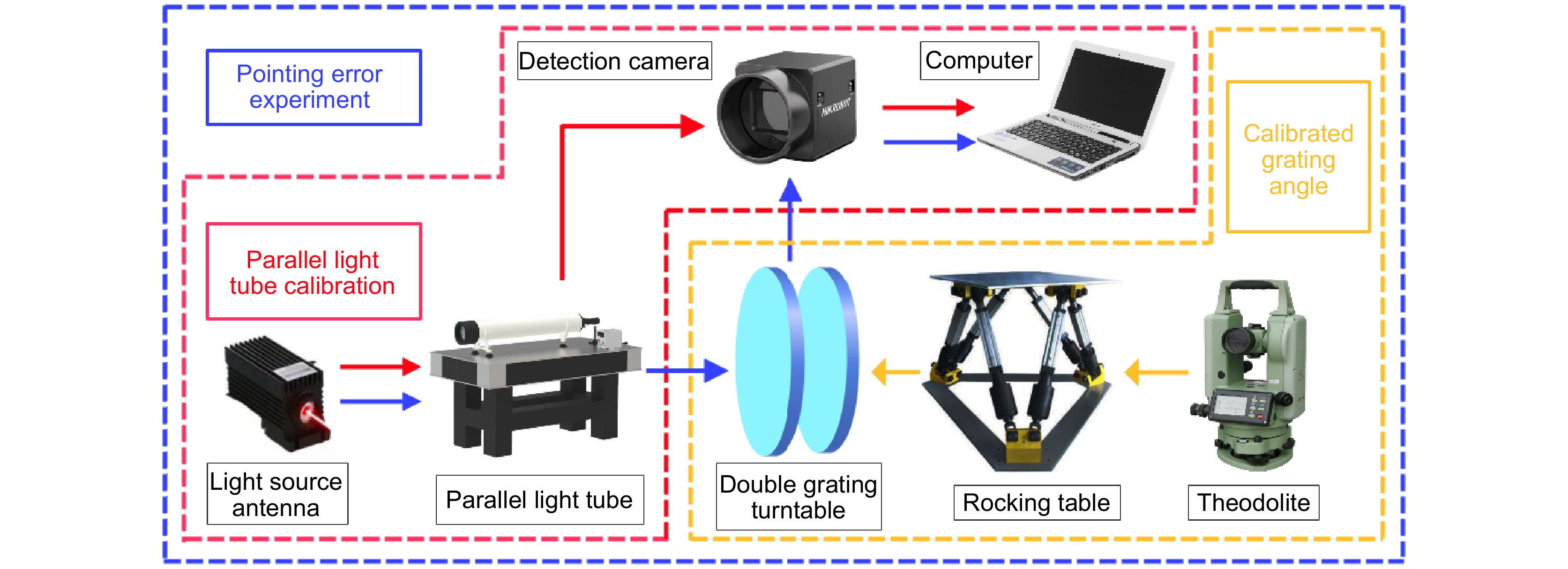
Figure 12.
Schematic diagram of double grating turntable and installation test. (a) Double grating turntable; (b) Double grating turntable installation; (c) Test site installation test site
-
Figure 13.
Experimental test process
-
Figure 14.
Double grating turntable pointing error test site
-
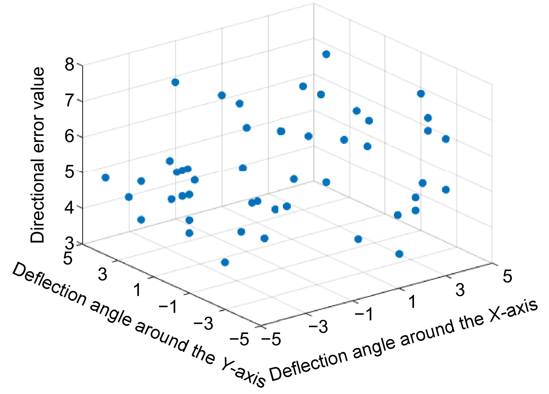
Figure 15.
Experimental data of pointing error
- Figure .


