
 E-mail Alert
 RSS
RSS
| Citation: |
Wang Shuai, Wang Bin, Liu Qingwen, et al. Advances of key technologies on optical reflectometry with ultra-high spatial resolution[J]. Opto-Electronic Engineering, 2018, 45(9): 170669. doi: 10.12086/oee.2018.170669

|
Advances of key technologies on optical reflectometry with ultra-high spatial resolution
-
Abstract
As the core technology of distributed fiber-optic sensing, optical reflectometry may realize the non-destructive measurement at a remote position. It can be used to retrieve the distributed information such as reflectance, refractive index, polarization state along the optical fiber, and to diagnose the irregular "event" on fiber-optic links. For some high-end fields, such as the fault diagnosis on the fiber-to-the-home (FTTH) access network, the deformation monitoring on large generating units and large transformers, and the security monitoring on structures of airplane wings, the requirements on spatial resolution and measurement range of the sensing technologies are very high. In this paper, we summarized the research status on state-of-art optical reflectometry technologies, and reviewed the advances of key technologies on optical reflectometry with ultra-high spatial resolution and long measurement range. We proposed three different methods to improve the performance, and tried to promote their applications on distributed fiber-optic sensing systems. -

-
References
[1] Barnoski M K, Jensen S M. Fiber waveguides: a novel technique for investigating attenuation characteristics[J]. Applied Optics, 1976, 15(9): 2112-2115. doi: 10.1364/AO.15.002112 [2] Liokumovich L B, Ushakov N A, Kotov O I, et al. Fundamentals of optical fiber sensing schemes based on coherent optical time domain reflectometry: signal model under static fiber conditions[J]. Journal of Lightwave Technology, 2015, 33(17): 3660-3671. doi: 10.1109/JLT.2015.2449085 [3] Martins H F, Martín-López S, Corredera P, et al. Phase-sensitive optical time domain reflectometer assisted by first-order Raman amplification for distributed vibration sensing over > 100 km[J]. Journal of Lightwave Technology, 2014, 32(8): 1510-1518. doi: 10.1109/JLT.2014.2308354 [4] Martins H F, Martin-Lopez S, Corredera P, et al. Coherent noise reduction in high visibility phase-sensitive optical time domain reflectometer for distributed sensing of ultrasonic waves[J]. Journal of Lightwave Technology, 2013, 31(23): 3631-3637. doi: 10.1109/JLT.2013.2286223 [5] Eickhoff W, Ulrich R. Optical frequency domain reflectometry in single‐mode fiber[J]. Applied Physics Letters, 1981, 39(9): 693-695. doi: 10.1063/1.92872 [6] Takada K, Yokohama I, Chida K, et al. New measurement system for fault location in optical waveguide devices based on an interferometric technique[J]. Applied Optics, 1987, 26(9): 1603-1606. doi: 10.1364/AO.26.001603 [7] Soller B J, Gifford D K, Wolfe M S, et al. High resolution optical frequency domain reflectometry for characterization of components and assemblies[J]. Optics Express, 2005, 13(2): 666-674. doi: 10.1364/OPEX.13.000666 [8] Bethea C G, Levine B F, Cova S, et al. High-resolution and high-sensitivity optical-time-domain reflectometer[J]. Optics Letters, 1988, 13(3): 233-235. doi: 10.1364/OL.13.000233 [9] Legré M, Thew R, Zbinden H, et al. High resolution optical time domain reflectometer based on 1.55 μm up-conversion photon-counting module[J]. Optics Express, 2007, 15(13): 8237-8242. doi: 10.1364/OE.15.008237 [10] Shentu G L, Sun Q C, Jiang X, et al. 217 km long distance photon-counting optical time-domain reflectometry based on ultra-low noise up-conversion single photon detector[J]. Optics Express, 2013, 21(21): 24674-24679. doi: 10.1364/OE.21.024674 [11] Zhao Q Y, Hu J H, Zhang X P, et al. Photon-counting optical time-domain reflectometry with superconducting nanowire single-photon detectors[C]//Proceedings of the IEEE 14th International Superconductive Electronics Conference (ISEC), 2013: 1-3. [12] Wang Y C, Wang B J, Wang A B. Chaotic correlation optical time domain reflectometer utilizing laser diode[J]. IEEE Photonics Technology Letters, 2008, 20(19): 1636-1638. doi: 10.1109/LPT.2008.2002745 [13] Wang Z N, Fan M Q, Zhang L, et al. Long-range and high-precision correlation optical time-domain reflectometry utilizing an all-fiber chaotic source[J]. Optics Express, 2015, 23(12): 15514-15520. doi: 10.1364/OE.23.015514 [14] Zhang L M, Pan B W, Chen G C, et al. Long-range and high-resolution correlation optical time-domain reflectometry using a monolithic integrated broadband chaotic laser[J]. Applied Optics, 2017, 56(4): 1253-1256. doi: 10.1364/AO.56.001253 [15] Wang S, Fan X Y, Liu Q W, et al. Distributed fiber-optic vibration sensing based on phase extraction from time-gated digital OFDR[J]. Optics Express, 2015, 23(26): 33301-33309. doi: 10.1364/OE.23.033301 [16] Liu Q W, Fan X Y, He Z Y. Time-gated digital optical frequency domain reflectometry with 1.6-m spatial resolution over entire 110-km range[J]. Optics Express, 2015, 23(20): 25988-25995. [17] Wang B, Fan X Y, Wang S, et al. Millimeter-resolution long-range OFDR using ultra-linearly 100 GHz-swept optical source realized by injection-locking technique and cascaded FWM process[J]. Optics Express, 2017, 25(4): 3514-3524. doi: 10.1364/OE.25.003514 [18] Wang S, Fan X Y, He Z Y. Ultrahigh resolution optical reflectometry based on linear optical sampling technique with digital dispersion compensation[J]. IEEE Photonics Journal, 2017, 9(6): 6804710. [19] Wang S, Fan X Y, Wang B, et al. Sub-THz-range linearly chirped signals characterized using linear optical sampling technique to enable sub-millimeter resolution for optical sensing applications[J]. Optics Express, 2017, 25(9): 10224-10233. doi: 10.1364/OE.25.010224 [20] Koshikiya Y, Fan X Y, Ito F. Long range and cm-level spatial resolution measurement using coherent optical frequency domain reflectometry with SSB-SC modulator and narrow linewidth fiber laser[J]. Journal of Lightwave Technology, 2008, 26(18): 3287-3294. doi: 10.1109/JLT.2008.928916 [21] Fan X Y, Koshikiya Y, Ito F. Phase-noise-compensated optical frequency-domain reflectometry[J]. IEEE Journal of Quantum Electronics, 2009, 45(6): 594-602. doi: 10.1109/JQE.2009.2013114 [22] Dorrer C, Kilper D C, Stuart H R, et al. Linear optical sampling[J]. IEEE Photonics Technology Letters, 2003, 15(12): 1746-1748. doi: 10.1109/LPT.2003.819729 -
Overview

Overview: As the core technology of distributed fiber-optic sensing, optical reflectometry may realize the non-destructive measurement at a remote position. It can be used to retrieve the distributed information such as reflectance, refractive index, polarization state along the optical fiber, and to diagnose the irregular "event" on fiber-optic links. In this paper, we summarized the research status on state-of-art optical reflectometry technologies, and reviewed the advances of key technologies on optical reflectometry with ultra-high spatial resolution and long measurement range. We proposed three different methods to improve the performance, and tried to promote their applications on distributed fiber-optic sensing systems.
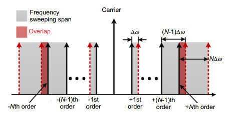
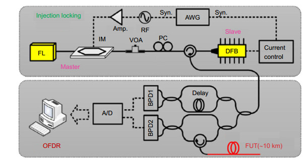
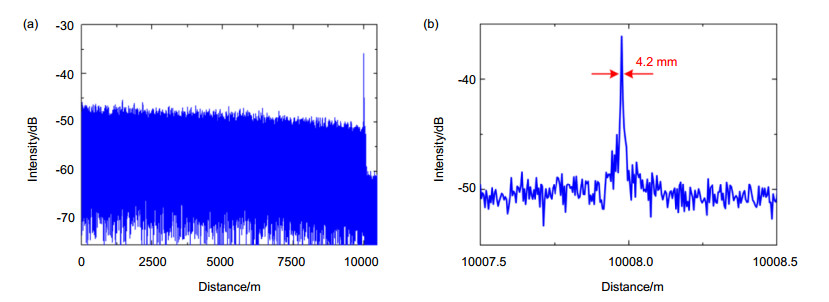
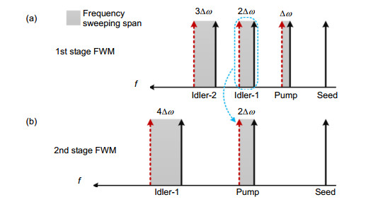
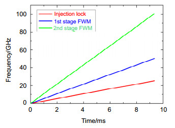
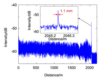
Firstly, we propose and demonstrate a millimeter-resolution long-range optical frequency domain reflectometry (OFDR) using an ultra-linearly 100 GHz swept optical source realized by injection-locking technique and cascaded four-wave-mixing (FWM) process. The ultra-linear swept source is realized using an external modulation method with a linearly swept radio frequency (RF) signal. By using the injection-locked frequency swept laser as the optical source of OFDR, we obtain a spatial resolution of 4.2 mm over 10 km measurement range. To further improve the spatial resolution, FWM process is used to broaden the frequency sweeping span. A frequency sweeping span of ~100 GHz is achieved with cascaded FWM. We demonstrate a 1.1 mm spatial resolution over 2 km measurement range with the proposed ultra-linearly swept optical source.
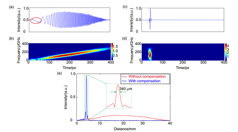
Then, we demonstrate an ultra-high-resolution optical time domain reflectometry (OTDR) system by using a mode-locked laser as the pulse source and a linear optical sampling technique to detect the reflected signals. Taking advantage of the ultrashort input pulse, the large detection-bandwidth, as well as the low timing jitter of linear optical sampling system, a sub-mm spatial resolution is achieved. As the pulse-width is broadened with the increase of distance due to the chromatic dispersion and the large bandwidth of the ultrashort pulse, by adopting digital chromatic dispersion compensation, we achieved a spatial resolution of 340 mm when measuring the reflector at 10 km.
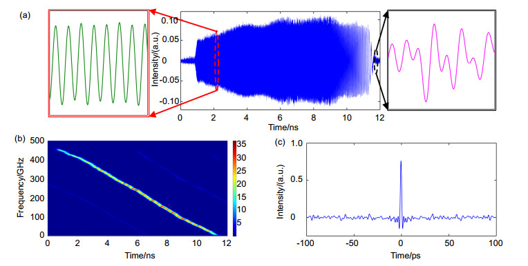
The final method is based on linear optical sampling and pulse compression method. We propose an all-optic sub-THz-range linearly chirped optical source and a high-bandwidth detection system to characterize it. Taking advantage of the chromatic dispersion effect, ultrashort optical pulses are stretched to be ~10-ns linearly chirped pulses with sub-THz range, which yields a large time-bandwidth product of 4500, a high compression ratio of 4167 and a chirp rate of 45 GHz/ns. A ultra-high spatial resolution of 120 μm with 150 m measurement range and 20.4 dB extinction ration is finally demonstrated.
-
Access History

Export File
Citation
Wang Shuai, Wang Bin, Liu Qingwen, et al. Advances of key technologies on optical reflectometry with ultra-high spatial resolution[J]. Opto-Electronic Engineering, 2018, 45(9): 170669. doi: 10.12086/oee.2018.170669
Format
Content
 DownLoad:


-
Figure 1.
The schematic illustration of the spectrum for the frequency sweep with high-order sidebands of external modulation[17]
-
Figure 2.
Experimental setup of the injection-locking scheme. FL: fiber laser; IM: intensity modulator; VOA: variable optical attenuator; PC: polarization controller; DFB: distributed feedback diode laser; Amp: RF amplifier; AWG: arbitrary waveform generator; FUT: fiber under test; BPD: balanced photodetector; A/D: analog-to-digital converter[17]
-
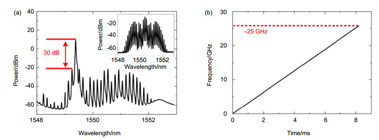
Figure 3.
(a) Optical spectrum of the slave laser which is injection locked to the 8th-order sideband of the master laser, and the inset is spectrum of the generated optical comb after IM; (b) Relative optical frequency as a function of time after the injection-locking[17]
-
Figure 4.
Experimental result of OFDR system. (a) Reflection trace; (b) Details of reflection peak around 10 km after using phase noise compensation (PNC) algorithm[17]
-
Figure 5.
Schematic of FWM[17]
-
Figure 6.
Relative optical frequency changes as a function of time[17]
-
Figure 7.
Measured reflection trace, and the inset shows the details of reflection peak at the end of the fiber under test (FUT) [17]
-
Figure 8.
Experimental illustration of linear optical sampling[18]
-
Figure 9.
Spatial resolution at different distances[18]
-
Figure 10.
(a) Reflection peak without chromatic dispersion (CD) compensation; (b) Time-frequency map of the reflection peak without CD compensation; (c) Reflection peak with CD compensation; (d) Time-frequency map of the reflection peak with CD; (e) Details of the reflection peak at 10 km with/without CD compensation[18]
-
Figure 11.
Experimental results. (a) A temporal frame of 10 ns linearly chirped pulse; (b) Shot time Fourier transformation (STFT) analysis of the linearly chirped pulse; (c) Calculated autocorrelation of the linearly chirped pulse[19]
-
Figure 12.
Experimental results. (a) 20 ns measurement of linearly chirped pulse with phase modulation; (b) STFT analysis of the linearly chirped pulse with phase modulation; (c) Calculated autocorrelation of the 20 ns linearly chirped pulse with phase modulation; (d) Autocorrelation of the 1544 ns time-aperture pulse[19]


