
 E-mail Alert
 RSS
RSS
-
摘要:
基于工业机器人的高灵活度光学加工系统可以加工大型或形状复杂的工件。但是,机器人自身定位误差特性会引起磨盘在工件表面上的定位精度降低,从而导致加工精度和加工效率的下降。本文研究了减小定位误差的方法并在仿真和光学加工实验中进行了验证。首先用API T3激光跟踪仪实时测出固定在机械臂末端的抛光工具在工作区域内的定位误差,以此为基础对驻留点进行误差补偿。实验测量结果表明,通过补偿后抛光工具的定位精度达到了光学精密加工的要求。通过仿真,计算了误差补偿前后磨盘的定位误差引起的驻留时间误差及去除量误差。结果表明,补偿之后,80%口径内去除量误差由整体去除量的3.68%降低至0.90%。最后,通过抛光实验验证了,经过位置误差的补偿并重新规划加工轨迹后,有效提高了加工效率,磨削量控制更精确。
 Abstract:
The high flexibility optical processing system based on the industrial robot can process large or complex workpieces. But the positioning error characteristics of the industrial robot will cause the decrease of positioning accuracy during grinding, which leads to a lower processing efficiency and processing precision. This paper studies the method of decreasing positioning error, which is verified by simulation and optical processing experiments: Firstly, the positioning error of the polishing tool that fixed at the end of robot in the working area is measured in real-time by using an API T3 laser tracker, and the errors of dwell points are compensated. The measurement experimental results show that the positioning accuracy of the polishing tool meets the high-precision optical processing requirements with the compensation. The dwell time error and the removal error caused by the positioning error before and after compensation are simulated, and the results show that after compensation, the removal error on 80% full aperture is reduced from 3.68% to 0.90%. At last, through the method of the position error compensation to replan the trajectory, the improvement of the processing efficiency and the accurate control on grinding are verified by polishing experiments.
-
Key words:
- optical processing robot /
- positioning accuracy /
- removal rate /
- polishing
-

Abstract: With the wide applications of optical systems, the demand for optical components is increasing. In order to meet the requirements of large quantity and low cost production of optical components, the optical manufacturing industry must find out a high-efficient, high-accuracy, economical and practical processing method. After years of development, many new technologies, such as ion beam, magneto-rheological fluid and air bag, have been produced in optical manufacturing. However, these processing equipments are often expensive, and some of these processing equipment cannot process large or complex workpieces because of space limitation. The high flexibility optical processing system based on the industrial robot, which combined industrial robot technology and computer numerical control technology, can process special optical components. Since the arm-rigid of now available robot is low, the defect of high positioning error in optical process leads to a lower processing efficiency and processing precision. This paper set the optical processing robot as the study object, and the following research works were carried out:
1) The positioning error of the polishing tool that fixed at the end of robot in circular flat area of Φ500 mm was measured in real-time by using an API Tracker 3 laser tracker. The spatial positions of dwell points were remeasured after the positioning error compensation. The measurement experimental results show that the positioning error of dwell points was reduced from 1158.3052 μm to 227.8408 μm.
2) According to above measurement of the positioning error before and after compensation, the dwell time error and the removal rate error caused by each group were calculated in optical processing simulation. The results show that after compensation, the removal rate error on 80% aperture was reduced from 3.68% to 0.90%.
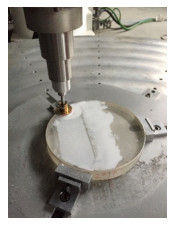
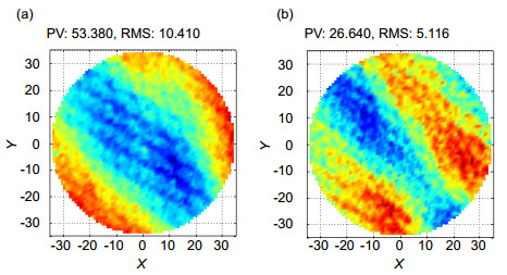
3) A K9 material flat mirror of Φ130 mm was polished uniformly in the polishing experiment. The actual removal rate was obtained by subtracting surface data before and after processing. Based on the above measurements, the position error of dwell points was compensated. After replanning the processing trajectory, the removal rate error was reduced from 53.38 nm to 26.64 nm. The processing accuracy was improved by compensating the positioning error.
-

-
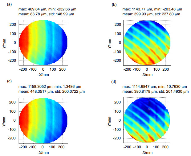
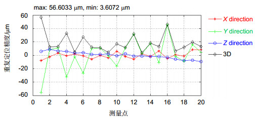
图 4 定位误差测量结果. (a) X方向误差. (b) Y方向误差. (c)距离误差. (d)距离误差(第二次测量结果).
Figure 4. Positioning error measurement results. (a) X-direction error. (b) Y-direction error. (c) Distance error. (d) Distance error (The second measurement result).
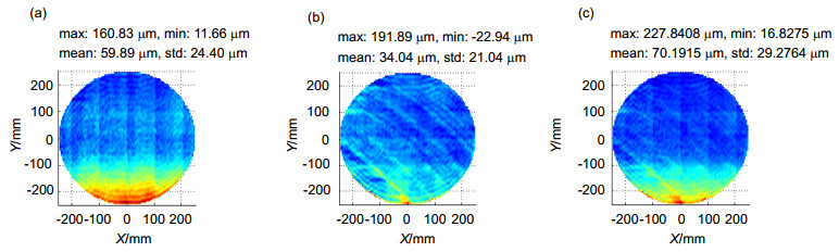
图 6 定位误差补偿结果. (a) X方向误差. (b) Y方向误差. (c)距离误差.
Figure 6. Positioning error compensation results. (a) X-direction error. (b) Y-direction error. (c) Distance error
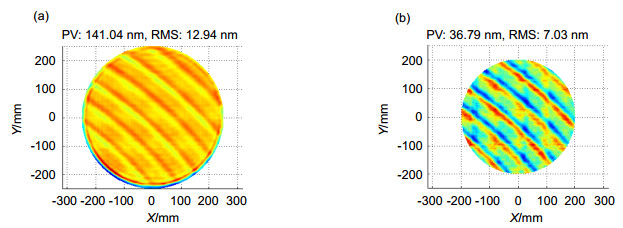
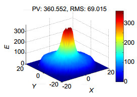
图 10 去除量误差. (a)全口径去除量误差. (b) 80%口径去除量误差.
Figure 10. The removal rate error. (a) Full aperture removal rate error. (b) 80% aperture removal rate error.
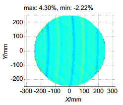
图 11 补偿定位误差之后的去除量误差. (a)全口径去除量误差. (b) 80%口径去除量误差.
Figure 11. The removal rate error after compensating the positioning error. (a) Full aperture removal rate error. (b) 80% aperture removal rate error.
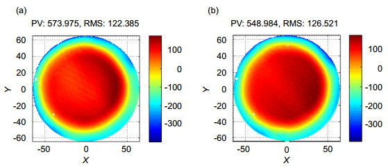
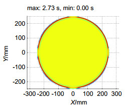
图 13 (a) 补偿前和(b)补偿后的全口径去除量.
Figure 13. Full aperture removal rate before compensation (a) and after compensation (b).
-
[1] Jones R A. Optimization of computer controlled polishing[J]. Applied Optics, 1977, 16(1): 218–224. doi: 10.1364/AO.16.000218
[2] 王健, 郭隐彪, 朱睿.光学非球面元件机器人柔性抛光技术[J].厦门大学学报(自然科学版), 2010, 49(5): 636–639. http://dspace.xmu.edu.cn/handle/2288/105258
Wang Jian, Guo Yinbiao, Zhu Rui. Research on robotic polishing of optic aspheric component[J]. Journal of Xiamen University (Natural Science), 2010, 49(5): 636–639. http://dspace.xmu.edu.cn/handle/2288/105258
[3] Kelm A, Boerret R, Sinzinger S. Improving the polishing accuracy by determining the variance of the friction coef-ficient[J]. Journal of the European Optical Society Rapid Publications, 2012, 7: 12049. doi: 10.2971/jeos.2012.12049
[4] Derst G, Giggel V. Fabrication technologies for large optical components at Carl Zeiss Jena GmbH[J]. Proceedings of SPIE, 2010, 7739: 773903. https://www.spiedigitallibrary.org/redirect/proceedings/proceeding?doi=10.1117/12.857067
[5] Walker D, Yu G Y, Gray C, et al. Process Automation in Computer Controlled Polishing[J]. Journal of the European Optical Society Rapid Publications, 2016, 11: 684–689. https://www.scientific.net/AMR.1136.684
[6] Walker D, Dunn C, Yu Guoyu, et al. The role of robotics in computer controlled polishing of large and small optics[J]. Proceedings of SPIE, 2015, 9575: 95750B. https://www.spiedigitallibrary.org/conference-proceedings-of-spie/9575/1/The-role-of-robotics-in-computer-controlled-polishing-of-large/10.1117/12.2189203.full
[7] Wang Wei, Yu Guoyu, Xu Min, et al. Coordinate transformation of an industrial robot and its application in deterministic optical polishing[J]. Optical Engineering, 2014, 53(5): 055102. https://www.spiedigitallibrary.org/journals/Optical-Engineering/volume-53/issue-05/055102/Coordinate-transformation-of-an-industrial-robot-and-its-application-in/10.1117/1.OE.53.5.055102.pdf
[8] 沙晟春, 郭晓凌.工业机器人光学加工中边缘问题的解决方法[J].科学技术与工程, 2012, 12(12): 2800–2804. doi: 10.3969/j.issn.1671-1815.2012.12.006
Sha Shengchun, Guo Xiaoling. The solution to the edge figuring of optical fabrication based on industrial robots[J]. Science Technology and Engineering, 2012, 12(12): 2800–2804. doi: 10.3969/j.issn.1671-1815.2012.12.006
[9] 雷存栋, 郑列华.基于机器人技术控制大口径光学表面中频误差的方法[J].科学技术与工程, 2014, 14(25): 83–86. doi: 10.3969/j.issn.1671-1815.2014.25.016
Lei Cundong, Zheng Liehua. A method for controlling mid-spatial frequency errors in big aperture optical surface base on robot technology[J]. Science Technology and Engineering, 2014, 14(25): 83–86. doi: 10.3969/j.issn.1671-1815.2014.25.016
[10] Tian Fengjie, Li Zhenguo, Lv Chong, et al. Polishing pressure investigations of robot automatic polishing on curved surfaces[J]. The International Journal of Advanced Manufacturing Technology, 2016, 87(1–4): 639–646. https://link.springer.com/article/10.1007/s00170-016-8527-2
[11] Liu Haitao, Wan Yongjian, Zeng Zhige, et al. Freeform surface grinding and polishing by CCOS based on industrial robot[J]. Proceedings of SPIE, 2016, 9683: 96832D. doi: 10.1117/12.2243652
[12] 奚陶. 工业机器人运动学标定与误差补偿研究[D]. 武汉: 华中科技大学, 2012.
[13] 邓永刚. 工业机器人重复定位精度与不确定度研究[D]. 天津: 天津大学, 2014.
[14] Lim H K, Kim D H, Kim S R, et al. A practical approach to enhance positioning accuracy for industrial robots[C]// Proceedings of ICCAS-SICE, Fukuoka, Japan, 2009: 2268–2273.
[15] Preston F W. The theory and design of plate glass polishing machines[J]. Journal of the Society of Glass Technology, 1927, 11: 214-256. http://citeseerx.ist.psu.edu/showciting?cid=2184383
[16] 汉语. 离轴非球面数控加工关键技术研究[D]. 北京: 中国科学院研究生院, 2010.
[17] 周林, 解旭辉, 戴一帆, 等.光学平面镜面离子束修形中速度模式的实现[J].机械工程学报, 2009, 45(7): 152–156. http://www.wanfangdata.com.cn/details/detail.do?_type=perio&id=jxgcxb200907024
Zhou Lin, Xie Xuhui, Dai Yifan, et al. Realization of velocity mode in flat optics machining using ion beam[J]. Journal of Mechanical Engineering, 2009, 45(7): 152–156. http://www.wanfangdata.com.cn/details/detail.do?_type=perio&id=jxgcxb200907024
[18] White R L. Image restoration using the damped Richard-son-Lucy method[J]. Proceedings of SPIE, 1994, 2198: 1348. https://www.researchgate.net/publication/235890204_Image_restoration_using_the_damped_Richardson-Lucy_method
-
 下载:
下载:
 点击扫一扫
点击扫一扫
图(15)
计量
- 文章访问数: 7327
- PDF下载数: 3100
- 施引文献: 0


