
 E-mail Alert
 RSS
RSS
Research on a 30 times ratio continuous zoom television optical system adjustment technology
-
摘要:
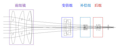
针对30倍连续变焦电视公差灵敏度高,装调难度大的问题,运用光学仿真方法分析各分离透镜偏心对光学系统MTF的影响。结果显示,前组镜中心偏差对系统像质影响敏感,会产生非对称像差。本文优选光机界面的结构形式,使透镜下表面自动定心,微调上表面将偏心控制在公差范围内。变倍组、补偿组作为运动组件,在变焦过程中光轴共轴性也是影响系统像质的关键因素。本文采用机械定心工装使运动组件的中心轴线与导杆轴线平行,再以前组镜透射光轴为基准,校正所有光学部件光轴与之共轴。光学系统经过精密装调,小视场像质分辨率达到2.43″,接近衍射分辨率极限。
 Abstract:
Aiming at the problem of high tolerance sensitivity and difficult adjustment of 30 times continuous zoom TV, the effects of eccentricity on the MTF (modulation transfer function) of the optical system were analyzed by optical software. The results show that the central error of the front mirror group is sensitive to the asymmetric aberration. In this paper, the structural form of the spacer ring machine program is optimized, so that the lower surface of the lens is automatically centering. As the moving component of the system, both zoom lens group and compensation lens group are the key factors affecting the system image quality during the zooming process. In this paper, mechanical centering tooling is used to make the central axis of the moving assembly parallel to the axis of the guide rod. The optical axis of all components is corrected by the optical axis of the front mirror group. The optical system is precisely adjusted, and the optical resolution of the small field of view reaches 2.43″, which is close to the limit of diffraction resolution.
-
Key words:
- continuous zoom /
- optical machine interface /
- centering method
-

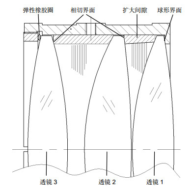
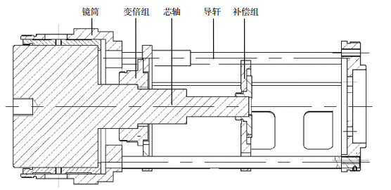
Overview: This paper introduces a kind of continuous zoom TV. The zoom ratio reaches 30 times and the ratio of total optical length to focal length of small field of view reaches 0.5. The smaller the optical compression ratio of the continuous zoom system is, the higher the tolerance sensitivity of the system is and the greater the difficulty of mounting and adjusting is. The traditional debugging method is that the transmission optical axis of the former set of mirrors is taken as the reference, and the optical axis of the adjusting group, the compensating group and the rear group are coaxial with the former set of mirrors. However, the image quality is poor and it is difficult to meet the use requirements. Eccentricity error of lens and coaxial error of optical motion module are the main factors affecting the image quality of continuous zoom TV. The effects of eccentricity on the MTF (modulation transfer function) of the optical system were analyzed by optical software. The results show that the central error of the front mirror group is sensitive to the asymmetric aberration. Because of the existence of machining and alignment errors, the lens of the system produces translation and tilt relative to the optical axis, so the system produces asymmetric aberration. The front mirror group consists of three double convex lenses. If the convex sphere of the lens is well matched with the optical-mechanical interface of the high-precision diaphragm, the spherical center of the lower surface of the lens is automatically located on the central axis of the diaphragm under gravity. Adjusting the inclination of the lens will not affect the position of the spherical center of the lower surface, thus realizing the automatic centering of the lower surface of the lens. In this paper, the structural form of the spacer ring machine program is optimized, so that the lower surface of the lens is automatically centering. As the moving component of the system, both zoom lens group and compensation lens group are the key factors affecting the system image quality during the zooming process. In this paper, mechanical centering tooling is used to make the central axis of the moving assembly parallel to the axis of the guide rod. The optical axis of all components is corrected by the optical axis of the front mirror group. The optical system is precisely adjusted, and the optical resolution of the small field of view reaches 2.43″, which is close to the limit of diffraction resolution.
-

-
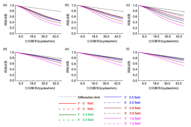
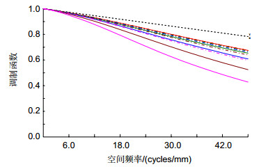
图 2 光学仿真结果。(a)前组镜透镜1;(b)前组镜透镜2;(c)前组镜透镜3;(d)变倍组;(e)补偿组;(f)后组
Figure 2. Optical simulation results. (a) Front group lens 1; (b) Front group lens 2; (c) Front group lens 3; (d) Multifocal group; (e) Compensating group; (f) Posterior group
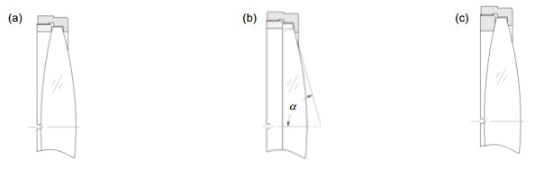
图 3 光机界面结构形式。(a)尖角界面;(b)相切界面;(c)球形界面
Figure 3. Interface structure of optical machine. (a) Sharp angle interface; (b) Tangent interface; (c) Spherical interface
表 1 前组镜实测中心偏结果
Table 1. Results of the test center of front group mirror
透镜 中心偏误差/(′) 透镜名称 曲率半径/mm X向 Y向 合计 透镜1 184.38 0.026 -0.058 0.064 -171.79 -0.081 -0.244 0.257 透镜2 104.23 0.062 0.049 0.079 -221.34 0.177 -0.068 0.189 透镜3 94.62 0.025 0.141 0.143 -234.43 -0.223 -0.131 0.259  下载: 导出CSV
表 2 实测运动组分光轴平行差结果
Table 2. Result of the parallel difference of the optical axis of the motion component
镜组 实测结果/(″) 变倍组 20.02 补偿组 26.03 后组 19.92
下载: 导出CSV
-
[1] 田海霞, 杨建峰, 马小龙.可见光变焦距电视光学系统设计[J].光子学报, 2008, 37(9):1797-1799. http://d.old.wanfangdata.com.cn/Periodical/gzxb200809020
Tian H X, Yang J F, Ma X L. Design for visible video zoom optical system[J]. Acta Photonica Sinica, 2008, 37(9):1797-1799. http://d.old.wanfangdata.com.cn/Periodical/gzxb200809020
[2] 赵阳, 巩岩, 胡宜宁.变焦距光学系统降低公差灵敏度的方法[J].光电工程, 2009, 36(7):121-125. doi: 10.3969/j.issn.1003-501X.2009.07.023
Zhao Y, Gong Y, Hu Y N. Method of tolerance sensitivity reduction of zoom optical system[J]. Opto-Electronic Engineering, 2009, 36(7):121-125. doi: 10.3969/j.issn.1003-501X.2009.07.023
[3] 李丽平, 唐良宝.补偿电视摄像机连续变焦中光轴偏移的一种新方法[J].光学技术, 2007, 33(S1):208-209. doi: 10.3321/j.issn:1002-1582.2007.z1.052
Li L P, Tang L B. A new method of compensation for optic axis offsets in continuous zoom TV camera[J]. Optical Technique, 2007, 33(S1):208-209. doi: 10.3321/j.issn:1002-1582.2007.z1.052
[4] 李志来, 薛栋林, 张学军.长焦距大视场光学系统的光机结构设计[J].光学 精密工程, 2008, 16(12):2485-2490. http://d.old.wanfangdata.com.cn/Periodical/gxjmgc200812027
Li Z L, Xue D L, Zhang X J. Optical and mechanical design for long focal length and wide-field optical system[J]. Optics and Precision Engineering, 2008, 16(12):2485-2490. http://d.old.wanfangdata.com.cn/Periodical/gxjmgc200812027
[5] 陶纯堪.变焦距光学系统设计[M].北京:国防工业出版社, 1988:153-163.
Tao C K. Zoom Lens Design[M]. Beijing:National Defense Industry Press, 1988:153-163.
[6] 张以谟.应用光学[M]. 2版.北京:机械工业出版社, 1987:576-596.
Zhang Y M. Applied Optics[M]. 2nd ed. Beijing:China Machine Press, 1987:576-596.
[7] 杨新军, 王肇圻, 母国光, 等.偏心和倾斜光学系统的像差特性[J].光子学报, 2005, 34(11):1658-1662. http://d.old.wanfangdata.com.cn/Periodical/gzxb200511014
Yang X J, Wang Z Q, Mu G G, et al. Aberration properties of the decentered and tilted optical systems[J]. Acta Photonica Sinica, 2005, 34(11):1658-1662. http://d.old.wanfangdata.com.cn/Periodical/gzxb200511014
[8] 宋岩峰, 孙卫平, 王国力.一种高分辨率电视制导连续变焦光学系统[J].应用光学, 2013, 34(2):203-208. doi: 10.5768/JAO201334.0201003
Song Y F, Sun W P, Wang G L. One kind of high resolution TV guided optical zoom system[J]. Journal of Applied Optics, 2013, 34(2):203-208. doi: 10.5768/JAO201334.0201003
[9] 约德.光机系统设计[M].周海宪, 程云芳, 译.北京: 机械工业出版社, 2008: 185-189.
Yoder P R, Jr. Opto-Mechanical Systems Design[M]. Zhou H X, Cheng Y F, trans. Beijing: China Machine Press, 2008: 185-189.
[10] 姚清华, 闫俊岑.高变倍比变焦光学系统设计[J].应用光学, 2015, 36(5):667-672. doi: 10.5768/JAO201536.0501001
Yao Q H, Yan J C. Design of zoom optical system with high zoom ratio[J]. Journal of Applied Optics, 2015, 36(5):667-672. doi: 10.5768/JAO201536.0501001
-

 点击扫一扫
点击扫一扫
图(7)
表(2)
计量
- 文章访问数: 13117
- PDF下载数: 2165
- 施引文献: 0


